Product Picture


Product Description
- 0.96 inch OLED screen with black and white, black or blue or yellow and blue color display
- 128x64 resolution for clear display and high contrast
- Large viewing angle: greater than 160° (one screen with the largest viewing angle in the display)
- Wide voltage supply (3V~5V), compatible with 3.3V and 5V logic levels, no level shifting chip required
- The default is 4-wire SPI bus, which can choose 3-wire SPI bus or IIC bus
- Ultra-low power consumption: normal display is only 0.06W (far below the TFT display)
- Military-grade process standards, long-term stable work
- Provides a rich sample program for STM32, C51, Arduino, Raspberry Pi and MSP430 platforms
- Provide underlying driver technical support
Product Parameters
| Name | Parameter |
| Display Color | White, blue, yellow and blue |
| SKU | MSP096B
MSP096W MSP096Y |
| Screen Size | 0.96(inch) |
| Screen Type | OLED |
| Driver IC | SSD1306 |
| Resolution | 128*64 (Pixel) |
| Module Interface | 3-line、4-line SPI、IIC interface |
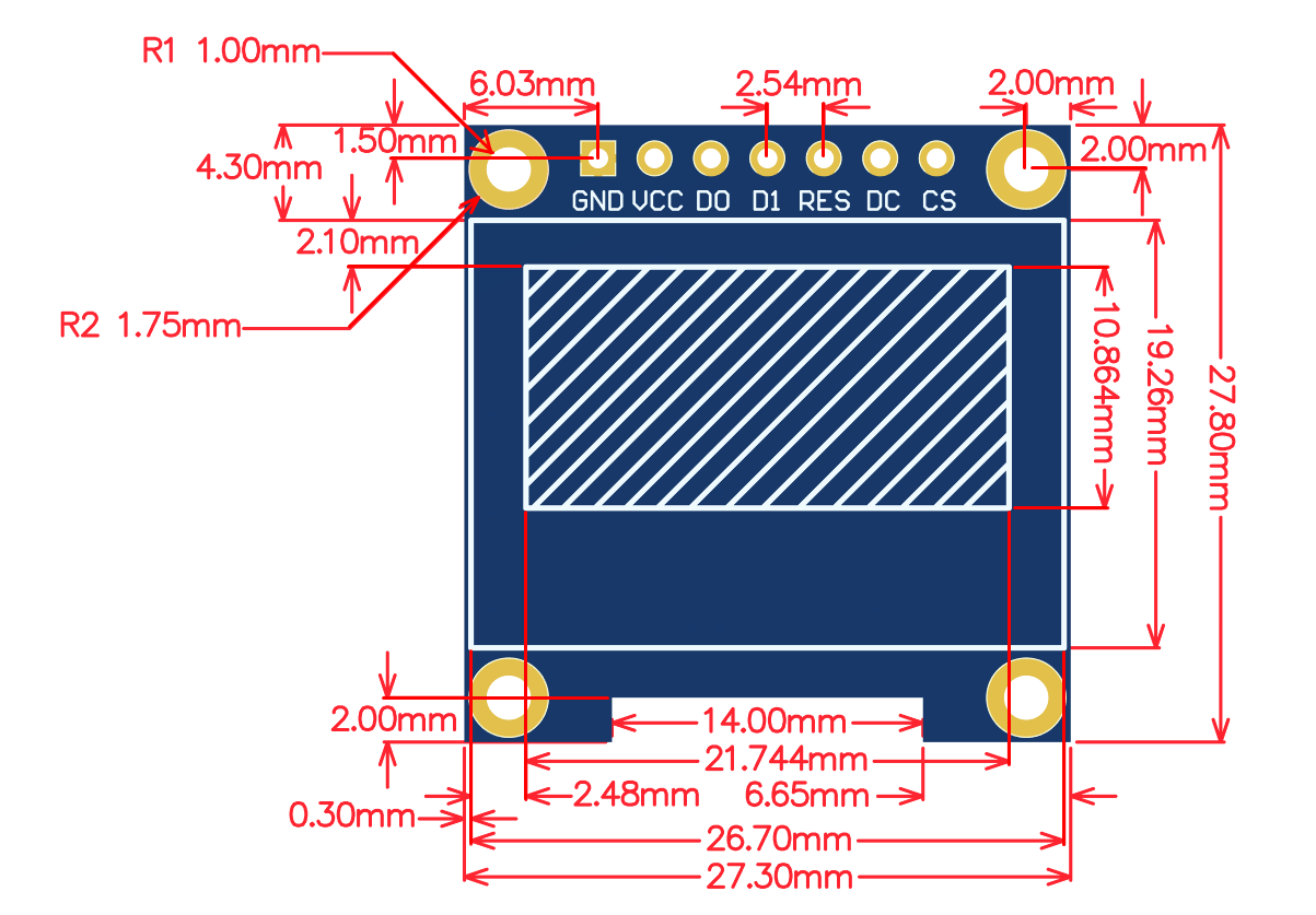
| Active Area | 21.744x10.864 (mm) |
| Touch Screen Type | have no touch screen |
| Touch IC | have no IC |
| Module PCB Size | 27.3x27.8 (mm) |
| Visual Angle | >160° |
| Operating Temperature | -20℃~60℃ |
| Storage Temperature | -30℃~70℃ |
| Operating Voltage | 3.3V~5V |
| Power Consumption | TBD |
| Rough Weight(Package containing) | 8(g) |
Interface Definition

|

|
|---|---|
| Picture 1. Module pin silk screen | Picture 2. Rear view of the module |
NOTE:
- 1.This module supports IIC, 3-wire SPI and 4-wire SPI interface bus mode switching (shown in red box in Figure 2). The details are as follows:
- A.Using 4.7K resistance to solder only R3 and R4 resistors, then choose 4-wire SPI bus interface (default);
- B.Using 4.7K resistance to solder only R2 and R3 resistors, then select 3-wire SPI bus interface;
- C.Using 4.7K resistance to solder only R1, R4, R6, R7, R8 resistors, then select the IIC bus interface;
- 2.After the interface bus mode is switched, you need to select the corresponding software and the corresponding wiring pins (as shown in Figure 1)
- for the module to operate normally. The corresponding wiring pins are described as follows:
- A.select the 4-wire SPI bus interface, all pins need to be used;
- B.select the 3-wire SPI bus interface, only the DC pin does not need to be used(it can not be connected), other pins need to be used;
- C.select the IIC bus interface, only need to use the four pins GND, VCC, D0, D1, At the same time, the RES pin is connected to the
- high level (can be connected to the VCC), the DC and CS pins are connected to the power GND;
| Number | Module Pin | Pin description |
| 1 | GND | OLED power ground |
| 2 | VCC | OLED power positive (3.3V~5V) |
| 3 | D0 | OLED SPI and IIC bus clock signals |
| 4 | D1 | OLED SPI and IIC bus data signals |
| 5 | RES | OLED reset signal, low level reset
(this pin need to connected to the high level (can be connected to the VCC) when selecting IIC bus) |
| 6 | DC | OLED command / data input select signal, high level: data, low level: command
(this pin is not required(it can not be connected) when selecting 3-wire SPI bus; this pin need to connected to the power GND when selecting IIC bus) |
| 7 | CS | OLED chip select signal, low level enable
(this pin need to connected to the power GND when selecting IIC bus) |
Product Documentation
- 0.96inch SPI_OLED Module User Manual
- 0.96inch OLED Specification(WHITE)
- 0.96inch OLED Specification(BLUE)
- 0.96inch OLED Specification(YELLOW and BLUE)
- 0.96inch SPI_OLED Module Size Picture
- 0.96inch SPI_OLED Module Schematic
- 0.96inch SPI_OLED Module OLED Schematic and PCB Package Library
- Driver IC SSD1306 Datasheet
Program Download
Reference Materials
- Arduino IDE software use illustration
- RaspberryPi GPIO library installation instructions
- Python Image Library installation instructions
- C51 Keil and stc-isp software use illustration
- STM32 keil software use illustration
- IAR_IDE and MspFet software use illustration
- PCtoLCD2002 software use illustration
- Image2Lcd software use illustration
- Chinese and English display modulo settings