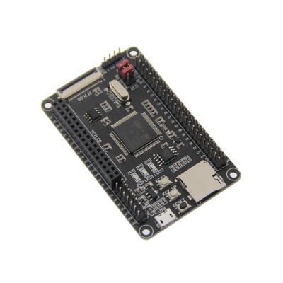
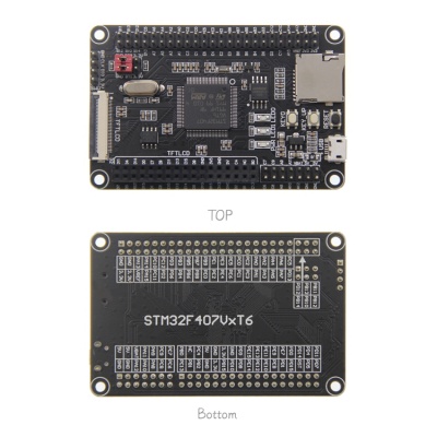
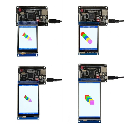
Product Picture
Product Features
- Small and exquisite appearance, convenient for various DIY projects
- Compatible with two CPUs: STM32F407VGT6 and STM32F407VET6
- The main frequency of CPU is as high as 168mhz, which is fast and powerful
- Rich storage resources, with internal SRAM: 192kb, internal flash: 1MB (STM32F407VGT6), 512KB (STM32F407VET6), external SPI flash: 8MB, external EEPROM: 256b
- The SD card can expand the storage space
- Support LCD pin insertion and FPC flexible cable connection
- Support using FSMC bus to drive LCD, fast display speed
- Support SWD and serial port download, easy debugging
- Support USB communication
- Expand the GPIO port to connect various peripherals conveniently
- Development resources are rich, easy to learn, easy to start
- Provide rich development information
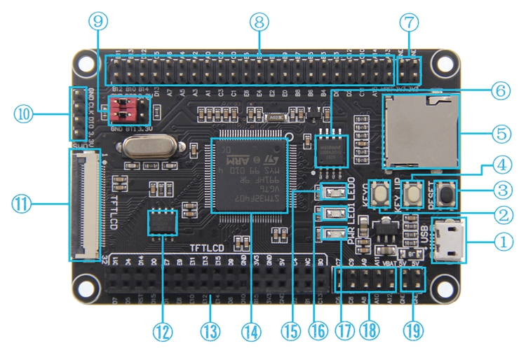
Hardware Description
| Number | Hardware Name | Description |
| ① | USB communication interface | It is used for USB communication between minimum system board and PC, including USB slave communication (minimum system board as U disk) and USB host (minimum system board as host). This interface can also be used as a power supply interface (except for USB host). |
| ② | Key0 test button | As a common test button, it can be used for key input function in the program. |
| ③ | Reset button | It is used to reset the main chip. In addition, when LCD TFT is directly inserted or FPC flexible cable is used, it can also reset LCD TFT |
| ④ | KEY_ Up test/wake up button | Used to wake up the main chip in standby mode. If the wake-up function is not used, it can be used as a normal key input. |
| ⑤ | SD card slot | It is used to insert SD card and expand the data storage space of the smallest system board. |
| ⑥ | W25Q64 SPI Flash | It is used to store font, picture and other user data and expand data storage space. |
| ⑦ | 3.3V power input / output pin | It is used to provide 3.3V power supply to the external, and it can also connect 3.3V power supply to the minimum system board from the outside. |
| ⑧ | IO extension | Used to connect external devices. |
| ⑨ | BT0 / BT1 boot select port | It is used to select the startup mode after the main chip is reset. |
| ⑩ | SWD download simulation interface | It is used to download and simulate the minimum system board. |
| ⑪ | TFT_ LCD FPC flat cable in line interface | Used to connect LCD module through FPC flexible cable. |
| ⑫ | 24C02 EEPROM | It is used to access some data which can not be lost after power failure, and has less requirements for reading speed and times. |
| ⑬ | TFT_ LCD pin in line interface | For direct insertion of LCD module through pin array |
| ⑭ | STM32F407VGT6/STM32F407VET6 main chip | Used to execute the program. It has a main frequency of 168mhz, internal SRAM: 192kb, internal flash: 1MB (stm32f407vgt6), 512KB (stm32f407vet6) |
| ⑮ | LED0 test lamp (blue) | It can be used to test GPIO output, indicate program running status or realize some lighting effects. |
| ⑯ | LED1 test lamp (blue) | It can be used to test GPIO output, indicate program running status or realize some lighting effects. |
| ⑰ | Power indicator (red) | Used to indicate the minimum system board power up. |
| ⑱ | IO extension | Used to connect external devices. |
| ⑲ | 5V power input / output pin | It is used to provide 5V power supply to the external, and can also connect 5V power supply to the minimum system board from the outside. |
Supported LCD models
- 2.4inch-MRB2408
- 2.8inch-MRB2801
- 2.8inch-MRB2802
- 3.2inch-MRB3205
- 3.5inch-MRB3503
- 3.5inch-MRB3511
- 3.5inch-MRB3512
- 3.97inch-MRB3973
- 4.0inch-MRB3951
- 4.0inch-MRB3952
Resource Download
Product Documentation
- STM32F407VxT6 minimum system board Instructions
- STM32F407VxT6 minimum system board size drawing
- STM32F407VxT6 minimum system board schematic
- STM32F407VxT6 minimum system board IO resource allocation table
- STM32F407VxT6 minimum system board schematic library
- STM32F407VxT6 minimum system board PCB package library
- STM32F407 data sheet
- STM32F407 English reference manual
Reference Material
- STM32 development board SWD package and debugging download instructions
- STM32 development board SWD download instructions
- STM32 development board serial port download instructions


