More actions
| (8 intermediate revisions by one other user not shown) | |||
| Line 76: | Line 76: | ||
|- | |- | ||
| align="center" |Rough Weight(Package containing) | | align="center" |Rough Weight(Package containing) | ||
| align="center" | | | align="center" |10(g) | ||
|} | |} | ||
| Line 89: | Line 89: | ||
|} | |} | ||
<br clear="all"> | <br clear="all"> | ||
'''NOTE:''' | |||
:1.This module supports IIC slave device address switching (shown in red box in Picture 4), as follows: | |||
::A.Solder the '''0x78''' side resistance, disconnect the '''0x7A''' side, then select the '''0x78''' slave address (default); | |||
::B.Solder the '''0x7A''' side resistance, disconnect the '''0x78''' side, then select the '''0x7A''' slave address; | |||
:2.The hardware switches the IIC slave device address, and the software also needs to be modified accordingly. | |||
::For details, see the test program description document or the user manual.. | |||
{| class="wikitable" border="1" style="width: 550px; background-color: white;" | {| class="wikitable" border="1" style="width: 550px; background-color: white;" | ||
| align="center" |Pin | | align="center" |Number | ||
| align="center" |Module Pin | |||
| align="center" |Pin description | | align="center" |Pin description | ||
|- | |- | ||
| align="center" |1 | |||
| align="center" |VCC | |||
| align="center" |OLED power positive (3.3V~5V) | |||
|- | |||
| align="center" |2 | |||
| align="center" |GND | | align="center" |GND | ||
| align="center" |OLED power ground | | align="center" |OLED power ground | ||
|- | |- | ||
| align="center" | | | align="center" |3 | ||
| align="center" |SCL | | align="center" |SCL | ||
| align="center" |OLED IIC bus clock signal | | align="center" |OLED IIC bus clock signal | ||
|- | |- | ||
| align="center" |4 | |||
| align="center" |SDA | | align="center" |SDA | ||
| align="center" |OLED IIC bus data signal | | align="center" |OLED IIC bus data signal | ||
| Line 110: | Line 122: | ||
==<font color="blue">Product Documentation</font> == | ==<font color="blue">Product Documentation</font> == | ||
* [http://www.lcdwiki.com/res/ | * [http://www.lcdwiki.com/res/MC130GX_VX/1.3inch_IIC_OLED_Module_MC130GX&MC130VX_User_Manual_EN.pdf '''1.3inch IIC_OLED Module User Manual'''] | ||
* [http://www.lcdwiki.com/res/ | * [http://www.lcdwiki.com/res/MC130GX_VX/OLED130W&OLED130B_SPEC.pdf '''1.3inch OLED Specification'''] | ||
* [http://www.lcdwiki.com/zh/images/ | * [http://www.lcdwiki.com/zh/images/d/d5/1.3OLED_Size.png '''1.3inch IIC_OLED Module Size Picture'''] | ||
* [http://www.lcdwiki.com/res/ | * [http://www.lcdwiki.com/res/MC130GX_VX/1.3inch_OLED_MC130VX_Schematic.pdf '''1.3inch IIC_OLED Module Schematic'''] | ||
* [http://www.lcdwiki.com/res/ | * [http://www.lcdwiki.com/res/MC130GX_VX/Altium_Package_Library.zip '''1.3inch IIC_OLED Module OLED Schematic and PCB Package Library'''] | ||
* [http://www.lcdwiki.com/res/ | * [http://www.lcdwiki.com/res/MC130GX_VX/SH1106_V2.3.pdf '''Driver IC SH1106 Datasheet'''] | ||
==<font color="blue">Program Download</font> == | ==<font color="blue">Program Download</font> == | ||
* [http://www.lcdwiki.com/res/Program/OLED/ | * [http://www.lcdwiki.com/res/Program/OLED/1.3inch/IIC_SH1106_MC130GX_VX_V1.0/1.3inch_IIC_OLED_Module_SH1106_MC130GX%26MC130VX_V1.0.zip '''1.3inch IIC_OLED Module Package'''] | ||
==<font color="blue">Reference Materials</font> == | ==<font color="blue">Reference Materials</font> == | ||
| Line 128: | Line 140: | ||
* [http://www.lcdwiki.com/res/PublicFile/C51_Keil%26stc-isp_Use_Illustration_EN.pdf '''C51 Keil and stc-isp software use illustration'''] | * [http://www.lcdwiki.com/res/PublicFile/C51_Keil%26stc-isp_Use_Illustration_EN.pdf '''C51 Keil and stc-isp software use illustration'''] | ||
* [http://www.lcdwiki.com/res/PublicFile/STM32_Keil_Use_Illustration_EN.pdf '''STM32 keil software use illustration'''] | * [http://www.lcdwiki.com/res/PublicFile/STM32_Keil_Use_Illustration_EN.pdf '''STM32 keil software use illustration'''] | ||
* [http://www.lcdwiki.com/res/PublicFile/IAR_IDE&MspFet_Use_Illustration_EN.pdf '''IAR_IDE and MspFet software use illustration'''] | |||
* [http://www.lcdwiki.com/res/PublicFile/PCtoLCD2002_Use_Illustration_EN.pdf '''PCtoLCD2002 software use illustration'''] | * [http://www.lcdwiki.com/res/PublicFile/PCtoLCD2002_Use_Illustration_EN.pdf '''PCtoLCD2002 software use illustration'''] | ||
* [http://www.lcdwiki.com/res/PublicFile/Image2Lcd_Use_Illustration_EN.pdf '''Image2Lcd software use illustration'''] | * [http://www.lcdwiki.com/res/PublicFile/Image2Lcd_Use_Illustration_EN.pdf '''Image2Lcd software use illustration'''] | ||
Latest revision as of 18:09, 22 August 2019
Product Picture


Product Description
- 1.3 inch OLED screen with black and white or black and blue color display
- 128x64 resolution for clear display and high contrast
- Large viewing angle: greater than 160° (one screen with the largest viewing angle in the display)
- Wide voltage supply (3V~5V), compatible with 3.3V and 5V logic levels, no level shifting chip required
- With IIC bus, only a few IOs can be used to light up the display
- Ultra-low power consumption: normal display is only 0.06W (far below the TFT display)
- Military-grade process standards, long-term stable work
- Provides a rich sample program for STM32, C51, Arduino, Raspberry Pi and MSP430 platforms
- Provide underlying driver technical support
Product Parameters
| Name | Parameter |
| Display Color | white/blue |
| SKU | MC130VW/MC130VB |
| Screen Size | 1.3(inch) |
| Screen Type | OLED |
| Driver IC | SH1106 |
| Resolution | 128*64 (Pixel) |
| Module Interface | IIC interface |
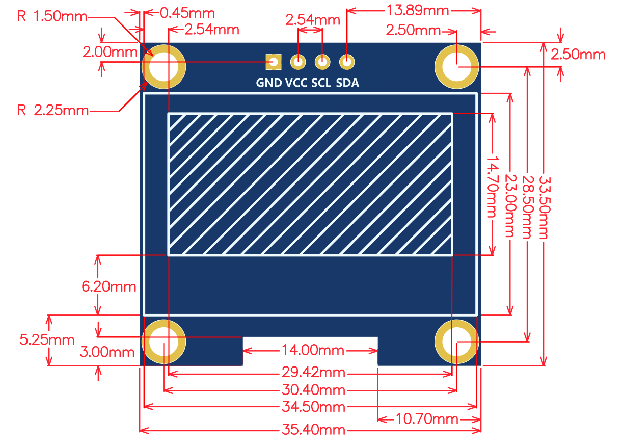
| Active Area | 29.42x14.7(mm) |
| Touch Screen Type | have no touch screen |
| Touch IC | have no IC |
| Module PCB Size | 33.50x35.40(mm) |
| Visual Angle | >160° |
| Operating Temperature | -20℃~60℃ |
| Storage Temperature | -30℃~70℃ |
| Operating Voltage | 3.3V~5V |
| Power Consumption | TBD |
| Rough Weight(Package containing) | 10(g) |
Interface Definition

|

|
|---|---|
| Picture 1. Module pin silk screen | Picture 2. Rear view of the module |
NOTE:
- 1.This module supports IIC slave device address switching (shown in red box in Picture 4), as follows:
- A.Solder the 0x78 side resistance, disconnect the 0x7A side, then select the 0x78 slave address (default);
- B.Solder the 0x7A side resistance, disconnect the 0x78 side, then select the 0x7A slave address;
- 2.The hardware switches the IIC slave device address, and the software also needs to be modified accordingly.
- For details, see the test program description document or the user manual..
| Number | Module Pin | Pin description |
| 1 | VCC | OLED power positive (3.3V~5V) |
| 2 | GND | OLED power ground |
| 3 | SCL | OLED IIC bus clock signal |
| 4 | SDA | OLED IIC bus data signal |
Product Documentation
- 1.3inch IIC_OLED Module User Manual
- 1.3inch OLED Specification
- 1.3inch IIC_OLED Module Size Picture
- 1.3inch IIC_OLED Module Schematic
- 1.3inch IIC_OLED Module OLED Schematic and PCB Package Library
- Driver IC SH1106 Datasheet
Program Download
Reference Materials
- Arduino IDE software use illustration
- RaspberryPi GPIO library installation instructions
- Python Image Library installation instructions
- C51 Keil and stc-isp software use illustration
- STM32 keil software use illustration
- IAR_IDE and MspFet software use illustration
- PCtoLCD2002 software use illustration
- Image2Lcd software use illustration
- Chinese and English display modulo settings