Difference between revisions of "0.96inch OLED Module SKU:MC096GX"
(Created page with "{{lan | cn=http://www.lcdwiki.com/zh/0.96inch_OLED_Module_SKU:MC096GX | en=http://www.lcdwiki.com/0.96inch_OLED_Module_SKU:MC096GX...") |
|||
| Line 3: | Line 3: | ||
cn=http://www.lcdwiki.com/zh/0.96inch_OLED_Module_SKU:MC096GX | cn=http://www.lcdwiki.com/zh/0.96inch_OLED_Module_SKU:MC096GX | ||
| | | | ||
| − | en=http://www.lcdwiki.com/0.96inch_OLED_Module_SKU:MC096GX | + | en=http://www.lcdwiki.com/0.96inch_OLED_Module_SKU:MC096GX |
}} | }} | ||
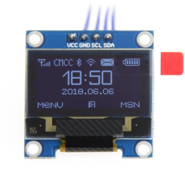
| + | ==<font color="blue">Product picture</font> == | ||
| + | [[File:MC096-22.jpg|600px]] | ||
| − | |||
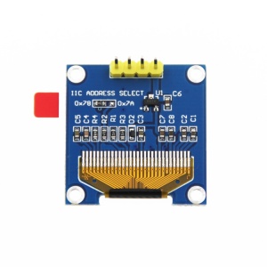
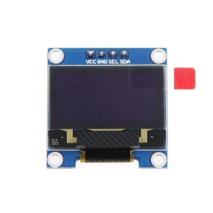
[[File:MC096-003.jpg|300px]] | [[File:MC096-003.jpg|300px]] | ||
| + | [[File:MC096-11.jpg|300px]] | ||
| − | ==<font color="blue"> | + | ==<font color="blue">Product description</font> == |
| − | * | + | *High resolution: 128x64 (have the same resolution as 12864, high PPI) |
| − | * | + | *Large viewing angle: greater than 160° (a screen with the largest viewing angle in the monitor) |
| − | * | + | *Ultra-low power consumption: it's 0.06w in normal condition(far less than TFT display) |
| − | * | + | *Wide voltage supply (3V~5V), 3.3V and 5V level logic compatible, no level shifter IC |
| − | * | + | *IIC interface and only requires 2 IOs to light up easily |
| − | * | + | *The range of working temperature is industrial (-20°C~70°C) |
| − | * | + | *Military-grade process standards, long-term work steadily |
| − | * | + | *Provide rich multi-platform routines and the technology support of underlying driver |
| − | * | + | *Have three color display schemes of yellow and blue,white,blue to choose from |
| − | ==<font color="blue"> | + | ==<font color="blue">Product parameters</font> == |
| − | {| class="wikitable" border="1" style="width: | + | {| class="wikitable" border="1" style="width: 30%; background-color: white;" |
| − | | align="center" | | + | | align="center" |name |
| − | | colspan="3" align="center" | | + | | colspan="3" align="center" |color category |
|- | |- | ||
| − | | | + | |display color |
| − | | | + | |white |
| − | | | + | |blue |
| − | | | + | |Blue and yellow |
|- | |- | ||
|SKU | |SKU | ||
| − | | style="color: #ff0000; " | | + | | style="color: #ff0000; " |MC096VW |
| − | | style="color: #ff0000; " | | + | | style="color: #ff0000; " |MC096VB |
| − | | style="color: #ff0000; " | | + | | style="color: #ff0000; " |MC096VY |
|- | |- | ||
| − | | | + | |size |
| colspan="3" |0.96(inch) | | colspan="3" |0.96(inch) | ||
|- | |- | ||
| − | | | + | |type |
| colspan="3" |OLED | | colspan="3" |OLED | ||
|- | |- | ||
| − | | | + | |OLED driver chip |
| colspan="3" |SSD1306 | | colspan="3" |SSD1306 | ||
|- | |- | ||
| − | | | + | |resolution |
| colspan="3" |128*64 (Pixel) | | colspan="3" |128*64 (Pixel) | ||
|- | |- | ||
| − | | | + | |Module interface |
| − | | colspan="3 | + | | colspan="3" |IIC,4PIN |
|- | |- | ||
| − | | | + | |Effective display area |
| colspan="3" |21.744x10.864(mm) | | colspan="3" |21.744x10.864(mm) | ||
|- | |- | ||
| − | | | + | |Module size |
| colspan="3" |27.3x27.8(mm) | | colspan="3" |27.3x27.8(mm) | ||
|- | |- | ||
| − | | | + | |Field of View |
| colspan="3" |>160° | | colspan="3" |>160° | ||
|- | |- | ||
| − | | | + | |Working temperature |
| colspan="3" | -20℃~70℃ | | colspan="3" | -20℃~70℃ | ||
|- | |- | ||
| − | | | + | |storage temperature |
| colspan="3" | -30℃~80℃ | | colspan="3" | -30℃~80℃ | ||
|- | |- | ||
| − | | | + | |Working voltage |
| colspan="3" |3.3V / 5V | | colspan="3" |3.3V / 5V | ||
|- | |- | ||
| − | | | + | |power dissipation |
| − | | colspan="3" | | + | | colspan="3" |Max:25mA,Min: 1.5mA |
|- | |- | ||
| − | | | + | |product weight |
| colspan="3" |15(g) | | colspan="3" |15(g) | ||
|} | |} | ||
| − | ==<font color="blue"> | + | ==<font color="blue">Interface definition</font> == |
| − | + | {| class="wikitable" border="1" style="width: 30%; background-color: white;" | |
| − | {| class="wikitable" border="1" style="width: | ||
|- | |- | ||
| align="center" |PIN | | align="center" |PIN | ||
| − | | align="center" | | + | | align="center" |label |
| − | | align="center" | | + | | align="center" |Pin description |
|- | |- | ||
| align="center" |1 | | align="center" |1 | ||
| − | | align="center" | | + | | align="center" |VCC |
| − | | | + | |OLED positive pole of power(3.3V~5V) |
|- | |- | ||
| align="center" |2 | | align="center" |2 | ||
| − | | align="center" | | + | | align="center" |GND |
| − | | | + | |OLED GND of power |
|- | |- | ||
| align="center" |3 | | align="center" |3 | ||
| align="center" |SCL | | align="center" |SCL | ||
| − | |OLED | + | |OLED clock signal of IIC bus |
|- | |- | ||
| align="center" |4 | | align="center" |4 | ||
| align="center" |SDA | | align="center" |SDA | ||
| − | |OLED | + | |OLED data signal of IIC bus |
|} | |} | ||
| − | ==<font color="blue"> | + | ==<font color="blue">Product size</font> == |
| − | + | Product size drawing:[http://www.lcdwiki.com/images/1/19/MC096-015.jpg 0.96 inch OLED Product size drawing] | |
| − | ==<font color="blue"> | + | ==<font color="blue">Hardware description</font> == |
| − | + | Hardware schematic:[http://www.lcdwiki.com/res/MC096VW/%E5%85%A8%E5%8A%A8%E7%94%B5%E5%AD%900.96%E5%AF%B8OLED%E6%98%BE%E7%A4%BA%E6%A8%A1%E5%9D%97%E5%8E%9F%E7%90%86%E5%9B%BE.pdf QD electronic 0.96 inch OLED display module hardware schematic.pdf] | |
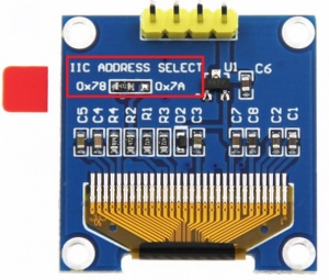
| − | + | IIC hardware adjustment instructions of device address to slave device: | |
| − | [[ | + | [[File:MC096-006.jpg|300x300px]] |
| + | As the picture shows,in the red rectangle,if the resistor is connected to 0x78, | ||
| − | + | it indicates that the IIC slave address is 0x78,if the resistor is connected to 0x7A, | |
| − | + | it indicates that the IIC slave address is 0x7A. | |
| − | |||
| − | + | ==<font color="blue">Using Instructions</font> == | |
| + | '''Arduino platform instructions''' | ||
| − | {| class="wikitable" border="1" style="width: | + | 1.Wiring instructions |
| − | ! colspan="2" | | + | |
| − | ! colspan="2" | | + | {| class="wikitable" border="1" style="width: 800px; background-color: white;" |
| + | ! colspan="2" |connection to UNO development board | ||
| + | ! colspan="2" |connect to Mega2560 development board | ||
|- | |- | ||
| − | ! align="center" | | + | ! align="center" |the pin on module |
| − | ! align="center" | | + | ! align="center" |the pin on UNO single chip |
| − | ! align="center" | | + | ! align="center" |the pin on module |
| − | ! align="center" | | + | ! align="center" |the pin on Mega2560 single chip |
|- | |- | ||
| align="center" |VCC | | align="center" |VCC | ||
| Line 150: | Line 154: | ||
|} | |} | ||
| − | + | 2.operation instructions | |
| + | |||
| + | a.Connect the OLED module to the Arduino development board according to the wiring instructions and then power on | ||
| − | + | b.[[#Driver download|Download the package]](see the driver download column for details), unzip and open the "1-Arduino测试程序\Arduino_OLED_Demo_UNO&Mega2560_IIC_V1.0\Example" folder, | |
| − | + | There are test programs inside,See the figure below (see the test procedure documentation for a description): | |
| − | + | [[file:MC096-016.jpg|750px]] | |
| − | + | c.Then open the "1-Arduino测试程序\Arduino_OLED_Demo_UNO&Mega2560_IIC_V1.0\Install libraries" folder, | |
| − | + | which contains the U8glib open source library, as shown in the following figure: | |
| − | [[ | + | [[file:MC096-038.jpg|750px]] |
| − | + | d.Copy U8glib to the directory where the Arduino IDE run lib is located, which can be viewed and set from the following figure: | |
| − | [[ | + | [[file:MC096-039.jpg|750px]] |
| − | + | e.Select any test program to run the test, for example select Example03-show_BMP test program | |
| − | + | f.When you open the test program,click tools-> Board to select the development board model,then click tools-> Port | |
| − | + | to select the com port to connect,as shown in the following figure: | |
| − | + | [[file:MC096-028.jpg|750px]] | |
| − | + | g.After both the development board model and the com port have been selected correctly,click the right arrow button to compile and download, | |
| − | + | as shown in the following figure: | |
| − | [[ | + | [[file:MC096-029.jpg|750px]] |
| − | + | h.When Done upload appears,the compilation and download are successful,as shown in the following figure: | |
| − | [[ | + | [[file:MC096-030.jpg|750px]] |
| − | + | i.The OLED module displays the pictures below,which indicates that the test program is running successfully and the operation is successful | |
| − | + | [[file:MC096-002.jpg|300px]] | |
| + | |||
| + | |||
| + | |||
| + | '''C51 platform instructions''' | ||
| + | |||
| + | 1.Wiring instructions | ||
{| class="wikitable" border="1" style="width: 500px; background-color: white;" | {| class="wikitable" border="1" style="width: 500px; background-color: white;" | ||
| − | ! | + | !the pin on module |
| − | ! align="center" | | + | ! align="center" |the pin on C51 single chip |
|- | |- | ||
| align="center" |VCC | | align="center" |VCC | ||
| Line 207: | Line 219: | ||
|} | |} | ||
| − | + | 2.operation instructions | |
| − | + | ||
| + | a.Connect the OLED module to the C51 development board according to the wiring instructions and then power on | ||
| + | |||
| + | b.[[#Driver download|Download the package]] (see the driver download column for details), unzip and open the "2-C51测试程序" folder, | ||
| − | + | [[file:MC096-020.jpg|750px]] | |
| − | + | c.There are two kinds of C51 single-chip test program,just choose one,for example,select STC12C5A60S2 microcontroller test program | |
| − | + | (for related instructions, see the test program documentation) | |
| − | + | d.Open the "C51_OLED_Demo_STC12C5A60S2_IIC_V1.0" folder and find the "OLED.uvproj" file,double-click to open the test program project | |
| − | + | e.Click the Compile button to compile the entire project.When "creating hex file from ".OBJ\TEST_OLED"..." appears, | |
| − | + | the compilation is successful, as shown in the following figure: | |
| − | + | [[file:MC096-031.jpg|750px]] | |
| − | + | f.Then open the STC-ISP software to download.The relevant settings are shown in the following figure: | |
| − | + | [[file:MC096-032.jpg|750px]] | |
| − | + | g.Then select the compiled hex file to burn.The burning file is in the directory of "C51_OLED_Demo_STC12C5A60S2_IIC_V1.0\OBJ", | |
| − | + | as shown in the following figure: | |
| − | [[ | + | [[file:MC096-033.jpg|750px]] |
| − | + | h.After the download is clicked,the MCU needs to be powered on again, when appear "successful operation", it means successful burning, | |
| − | + | the operation is shown in the following figure: | |
| − | + | [[file:MC096-034.jpg|750px]] | |
| − | + | i.The OLED module displays the pictures below,which indicates that the test program is running successfully and the operation is successful | |
| + | |||
| + | [[file:MC096-002.jpg|300px]] | ||
| + | |||
| + | '''STM32 platform instructions''' | ||
| + | 1.Wiring instructions | ||
{| class="wikitable" border="1" style="width: 500px; background-color: white;" | {| class="wikitable" border="1" style="width: 500px; background-color: white;" | ||
| − | ! | + | !the pin on module |
| − | ! align="center" | | + | ! align="center" |the pin on STM32 single chip |
|- | |- | ||
| align="center" |VCC | | align="center" |VCC | ||
| Line 258: | Line 278: | ||
|} | |} | ||
| − | + | 2.operation instructions | |
| − | + | ||
| + | a.Connect the OLED module to the STM32 development board according to the wiring instructions and then power on | ||
| + | |||
| + | b.[[#Driver download|Download the package]] (see the driver download column for details), unzip and open the "3-STM32测试程序" folder, | ||
| + | |||
| + | [[file:MC096-025.jpg|750px]] | ||
| + | |||
| + | c.there are two kinds of STM32 single-chip test program,just choose one,for example,select STM32F103RCT6 microcontroller test program | ||
| + | |||
| + | (for related instructions, see the test program documentation) | ||
| − | + | d.Open the "STM32_OLED_Demo_STM32F103RCT6_IIC_V1.0\USER" folder and find the "OLED.uvproj" file,double-click to open the test program project | |
| − | + | e.Click on the compile button to compile the entire project,and when "from ELF: creating hex file.\ OBJ\ TESTOLED.axf" appears, | |
| − | + | the compilation is successful, as shown in the following figure: | |
| − | + | [[file:MC096-035.jpg|750px]] | |
| − | + | f.Connect to JTAG and click the download button.When "Programming Done.Verify OK."appears, | |
| − | + | the download is successful, as shown in the following figure: | |
| − | + | [[file:MC096-036.jpg|750px]] | |
| − | + | g.The OLED module displays the pictures below,which indicates that the test program is running successfully and the operation is successful | |
| − | + | [[file:MC096-002.jpg|300px]] | |
| − | [ | + | ==<font color="blue">Driver download</font> == |
| + | baiduyun download:[https://pan.baidu.com/s/12cx6N4E-tSvCSD2xYyPpsA 0.96 inch OLED display module data of QD electronic V1.0(Extracted password:r5gi)] | ||
| − | + | Local download:[http://www.lcdwiki.com/res/MC096VW/%E5%85%A8%E5%8A%A8%E7%94%B5%E5%AD%900.96%E5%AF%B8OLED%E6%98%BE%E7%A4%BA%E6%A8%A1%E5%9D%97%E8%B5%84%E6%96%99V1.0.zip 0.96 inch OLED display module data of QD electronic V1.0] | |
| − | |||
| − | ==<font color="blue"> | + | ==<font color="blue">Common software description</font> == |
| − | + | the software description is in the software package and the download address as follows: | |
PCtoLCD2002:[http://www.lcdwiki.com/res/software/PCtoLCD2002.zip PCtoLCD2002] | PCtoLCD2002:[http://www.lcdwiki.com/res/software/PCtoLCD2002.zip PCtoLCD2002] | ||
Revision as of 10:33, 20 June 2018
Contents
Product picture
Product description
- High resolution: 128x64 (have the same resolution as 12864, high PPI)
- Large viewing angle: greater than 160° (a screen with the largest viewing angle in the monitor)
- Ultra-low power consumption: it's 0.06w in normal condition(far less than TFT display)
- Wide voltage supply (3V~5V), 3.3V and 5V level logic compatible, no level shifter IC
- IIC interface and only requires 2 IOs to light up easily
- The range of working temperature is industrial (-20°C~70°C)
- Military-grade process standards, long-term work steadily
- Provide rich multi-platform routines and the technology support of underlying driver
- Have three color display schemes of yellow and blue,white,blue to choose from
Product parameters
| name | color category | ||
| display color | white | blue | Blue and yellow |
| SKU | MC096VW | MC096VB | MC096VY |
| size | 0.96(inch) | ||
| type | OLED | ||
| OLED driver chip | SSD1306 | ||
| resolution | 128*64 (Pixel) | ||
| Module interface | IIC,4PIN | ||
| Effective display area | 21.744x10.864(mm) | ||
| Module size | 27.3x27.8(mm) | ||
| Field of View | >160° | ||
| Working temperature | -20℃~70℃ | ||
| storage temperature | -30℃~80℃ | ||
| Working voltage | 3.3V / 5V | ||
| power dissipation | Max:25mA,Min: 1.5mA | ||
| product weight | 15(g) | ||
Interface definition
| PIN | label | Pin description |
| 1 | VCC | OLED positive pole of power(3.3V~5V) |
| 2 | GND | OLED GND of power |
| 3 | SCL | OLED clock signal of IIC bus |
| 4 | SDA | OLED data signal of IIC bus |
Product size
Product size drawing:0.96 inch OLED Product size drawing
Hardware description
Hardware schematic:QD electronic 0.96 inch OLED display module hardware schematic.pdf
IIC hardware adjustment instructions of device address to slave device:
As the picture shows,in the red rectangle,if the resistor is connected to 0x78,
it indicates that the IIC slave address is 0x78,if the resistor is connected to 0x7A,
it indicates that the IIC slave address is 0x7A.
Using Instructions
Arduino platform instructions
1.Wiring instructions
| connection to UNO development board | connect to Mega2560 development board | ||
|---|---|---|---|
| the pin on module | the pin on UNO single chip | the pin on module | the pin on Mega2560 single chip |
| VCC | 5V | VCC | 5V |
| GND | GND | GND | GND |
| SCL | A5 | SCL | 21 |
| SDA | A4 | SDA | 20 |
2.operation instructions
a.Connect the OLED module to the Arduino development board according to the wiring instructions and then power on
b.Download the package(see the driver download column for details), unzip and open the "1-Arduino测试程序\Arduino_OLED_Demo_UNO&Mega2560_IIC_V1.0\Example" folder,
There are test programs inside,See the figure below (see the test procedure documentation for a description):
c.Then open the "1-Arduino测试程序\Arduino_OLED_Demo_UNO&Mega2560_IIC_V1.0\Install libraries" folder,
which contains the U8glib open source library, as shown in the following figure:
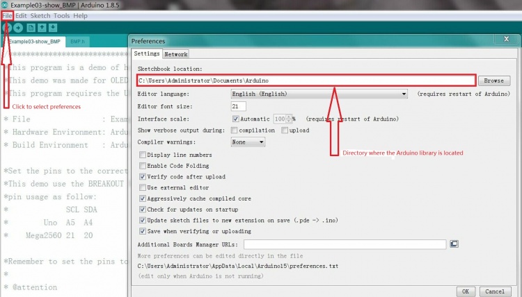
d.Copy U8glib to the directory where the Arduino IDE run lib is located, which can be viewed and set from the following figure:
e.Select any test program to run the test, for example select Example03-show_BMP test program
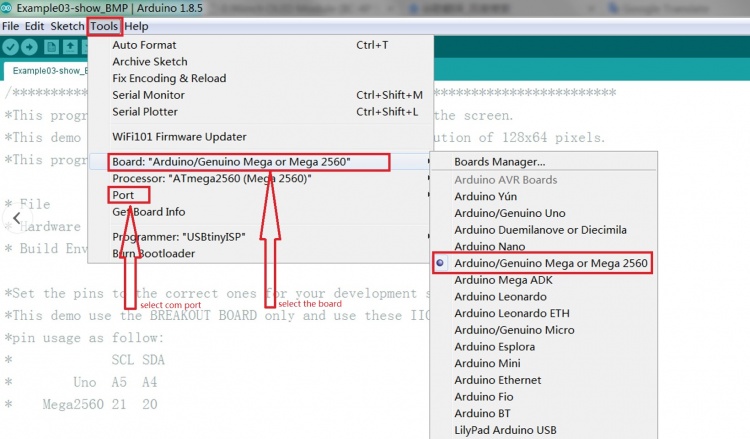
f.When you open the test program,click tools-> Board to select the development board model,then click tools-> Port
to select the com port to connect,as shown in the following figure:
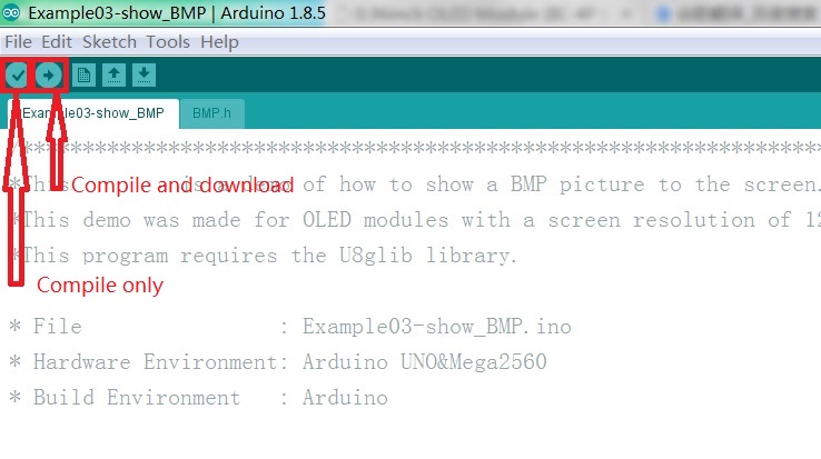
g.After both the development board model and the com port have been selected correctly,click the right arrow button to compile and download,
as shown in the following figure:
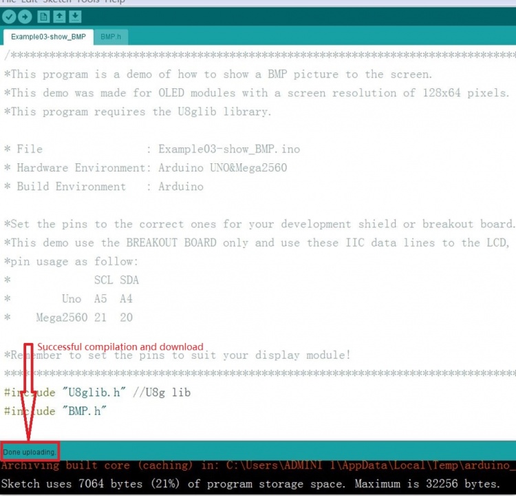
h.When Done upload appears,the compilation and download are successful,as shown in the following figure:
i.The OLED module displays the pictures below,which indicates that the test program is running successfully and the operation is successful
C51 platform instructions
1.Wiring instructions
| the pin on module | the pin on C51 single chip |
|---|---|
| VCC | 5V |
| GND | GND |
| SCL | P23 |
| SDA | P24 |
2.operation instructions
a.Connect the OLED module to the C51 development board according to the wiring instructions and then power on
b.Download the package (see the driver download column for details), unzip and open the "2-C51测试程序" folder,
c.There are two kinds of C51 single-chip test program,just choose one,for example,select STC12C5A60S2 microcontroller test program
(for related instructions, see the test program documentation)
d.Open the "C51_OLED_Demo_STC12C5A60S2_IIC_V1.0" folder and find the "OLED.uvproj" file,double-click to open the test program project
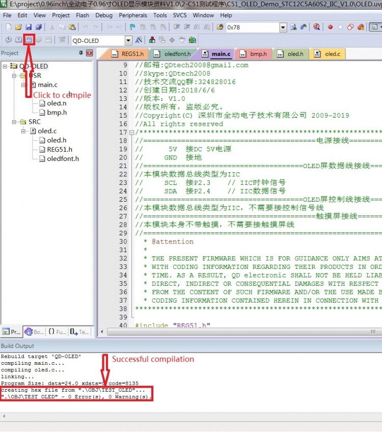
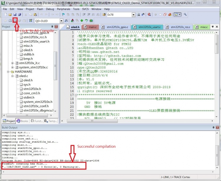
e.Click the Compile button to compile the entire project.When "creating hex file from ".OBJ\TEST_OLED"..." appears,
the compilation is successful, as shown in the following figure:
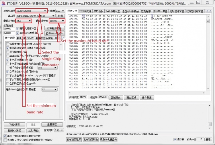
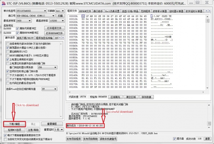
f.Then open the STC-ISP software to download.The relevant settings are shown in the following figure:
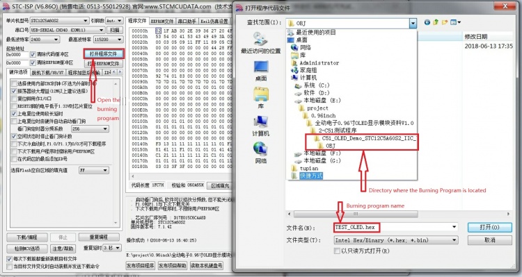
g.Then select the compiled hex file to burn.The burning file is in the directory of "C51_OLED_Demo_STC12C5A60S2_IIC_V1.0\OBJ",
as shown in the following figure:
h.After the download is clicked,the MCU needs to be powered on again, when appear "successful operation", it means successful burning,
the operation is shown in the following figure:
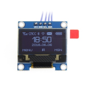
i.The OLED module displays the pictures below,which indicates that the test program is running successfully and the operation is successful
STM32 platform instructions 1.Wiring instructions
| the pin on module | the pin on STM32 single chip |
|---|---|
| VCC | 5V |
| GND | GND |
| SCL | PB13 |
| SDA | PB14 |
2.operation instructions
a.Connect the OLED module to the STM32 development board according to the wiring instructions and then power on
b.Download the package (see the driver download column for details), unzip and open the "3-STM32测试程序" folder,
c.there are two kinds of STM32 single-chip test program,just choose one,for example,select STM32F103RCT6 microcontroller test program
(for related instructions, see the test program documentation)
d.Open the "STM32_OLED_Demo_STM32F103RCT6_IIC_V1.0\USER" folder and find the "OLED.uvproj" file,double-click to open the test program project
e.Click on the compile button to compile the entire project,and when "from ELF: creating hex file.\ OBJ\ TESTOLED.axf" appears,
the compilation is successful, as shown in the following figure:
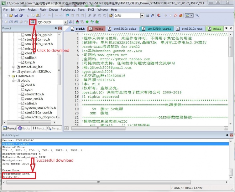
f.Connect to JTAG and click the download button.When "Programming Done.Verify OK."appears,
the download is successful, as shown in the following figure:
g.The OLED module displays the pictures below,which indicates that the test program is running successfully and the operation is successful
Driver download
baiduyun download:0.96 inch OLED display module data of QD electronic V1.0(Extracted password:r5gi)
Local download:0.96 inch OLED display module data of QD electronic V1.0
Common software description
the software description is in the software package and the download address as follows:
PCtoLCD2002:PCtoLCD2002
