| Line 151: | Line 151: | ||
==<font color="blue">Program Download</font> == | ==<font color="blue">Program Download</font> == | ||
* [http://www.lcdwiki.com/res/Program/Common_SPI/ | * [http://www.lcdwiki.com/res/Program/Common_SPI/4.0inch/SPI_ST7796S_MSP4020_4021_V1.0/4.0inch_SPI_Module_ST7796S_MSP4020%26MSP4021_V1.0.zip '''4.0 inch SPI Module Package'''] | ||
==<font color="blue">Reference Materials</font> == | ==<font color="blue">Reference Materials</font> == | ||
Latest revision as of 14:33, 27 September 2019
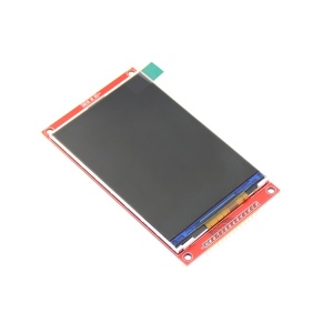
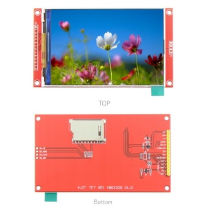
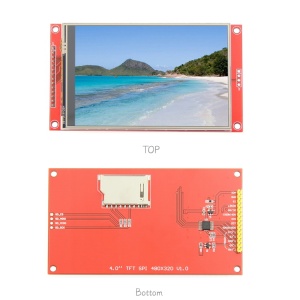
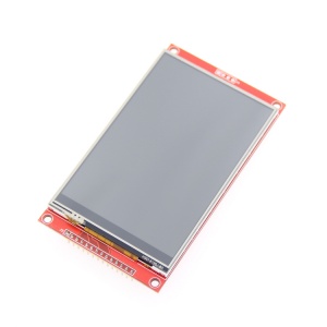
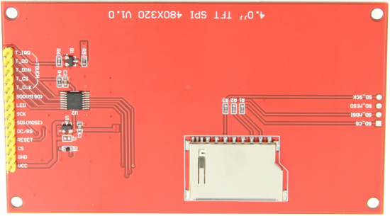
Product Picture
Product Description
- 4.0-inch color screen,support 65K color display,display rich colors
- 480X320 resolution, optional touch function
- Using the SPI serial bus, it only takes a few IOs to illuminate the display
- Easy to expand the experiment with SD card slot
- Provide a rich sample program
- Military-grade process standards, long-term stable work
- Provide underlying driver technical support
Product Parameters
| Name | Parameter |
| Display Color | RGB 65K color |
| SKU | have touch screen: MSP4021 |
| have no touch screen: MSP4020 | |
| Screen Size | 4.0(inch) |
| Screen Type | TFT |
| Driver IC | ST7796S |
| Resolution | 480*320 (Pixel) |
| Module Interface | 4-wire SPI interface |
| Active Area (AA area) | 55.68x83.52 (mm) |
| Module PCB Size | 61.74x108.04(mm) |
| Touch Screen Type | resistive touch screen |
| Touch IC | XPT2046 |
| VCC power voltage | 3.3V~5V |
| Power Consumption | TBD |
| Rough Weight(Package containing) | have touch screen: 71g |
| have no touch screen: 58g |
Interface Definition
| Number | Pin Label | Description |
| 1 | VCC | 5V/3.3V power input |
| 2 | GND | Ground |
| 3 | CS | LCD chip select signal, low level enable |
| 4 | RESET | LCD reset signal, low level reset |
| 5 | DC/RS | LCD command / data selection signal,
high level: command, low level: data |
| 6 | SDI(MOSI) | LCD SPI bus write data signal |
| 7 | SCK | LCD SPI bus clock signal |
| 8 | LED | Backlight control, high level lighting,
if not controlled, connect 3.3V always bright |
| 9 | SDO(MISO) | SPI bus read data signal, if you do not need to the read function, you can not connect it |
| (The following is the touch screen signal line wiring, if you do not need to touch function or the module itself does not have touch function, you can not connect them) | ||
| 10 | T_CLK | Touch SPI bus clock signal |
| 11 | T_CS | Touch screen chip select signal, low level enable |
| 12 | T_DIN | Touch SPI bus input |
| 13 | T_DO | Touch SPI bus output |
| 14 | T_IRQ | Touch screen interrupt signal, low level when touch is detected |
Product Documentation
- 4.0 inch SPI Module User Manual
- 4.0 inch TFT Specifications
- 4.0 inch SPI Module Size Picture
- 4.0 inch SPI Module Schematic
- 4.0inch SPI Module screen Schematic and PCB package library
- Driver IC ST7796S Data sheet
Program Download
Reference Materials
- Arduino IDE software use illustration
- C51 Keil and stc-isp software use illustration
- STM32 keil software use illustration
- PCtoLCD2002 software use illustration
- Image2Lcd software use illustration
- Chinese and English display modulo settings

