More actions
| (8 intermediate revisions by 2 users not shown) | |||
| Line 12: | Line 12: | ||
==<font color="blue">Product Description</font> == | ==<font color="blue">Product Description</font> == | ||
* | * CPU: STM32F103C8T6, main frequency: 72MHz, internal FLASH: 64KB, internal SRAM: 20KB | ||
* | * Small and delicate appearance, convenient for various DIY projects | ||
* | * Support SWD and serial download, easy to debug | ||
* | * Support SPI interface and IIC interface display module direct insertion | ||
* | * Extended GPIO port for easy connection to various peripherals | ||
* | * Rich development resources, easy to learn, easy to get started | ||
==<font color="blue">Product Parameters</font> == | ==<font color="blue">Product Parameters</font> == | ||
[[File:开发板STM32F103C8T6-功能图.jpg|750px]] | [[File:开发板STM32F103C8T6-功能图.jpg|750px]] | ||
{| class="wikitable" border="1" style="width: | {| class="wikitable" border="1" style="width: 90%; background-color: white;" | ||
|''' | |'''Serial number''' | ||
|''' | |'''Name''' | ||
|''' | |'''Description''' | ||
|- | |- | ||
|① | |① | ||
| | |J1 | ||
| | |Connect to the '''Common-SPI''' display module | ||
|- | |- | ||
|② | |② | ||
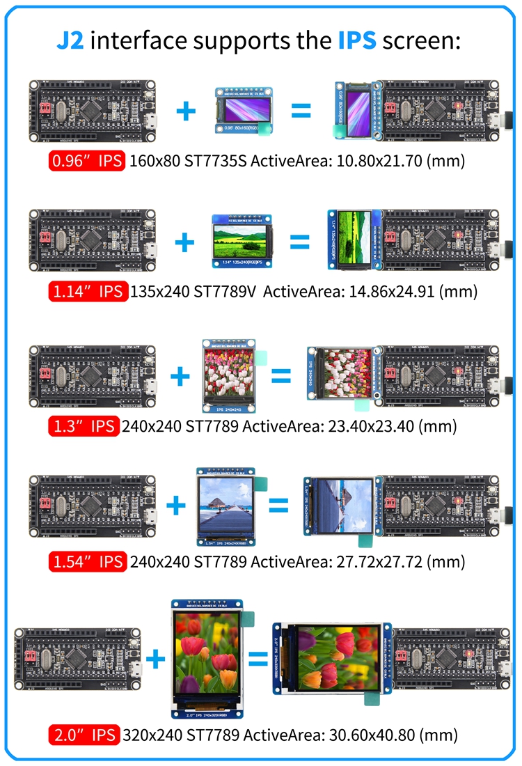
| | |J2 | ||
| | |Connect to the '''Common-SPI/IPS''' display module | ||
|- | |- | ||
|③ | |③ | ||
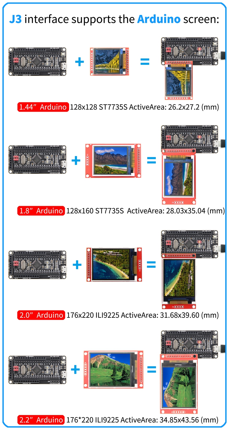
| | |J3 | ||
| | |Connect to the '''Arduino-SPI''' display module | ||
|- | |- | ||
|④ | |④ | ||
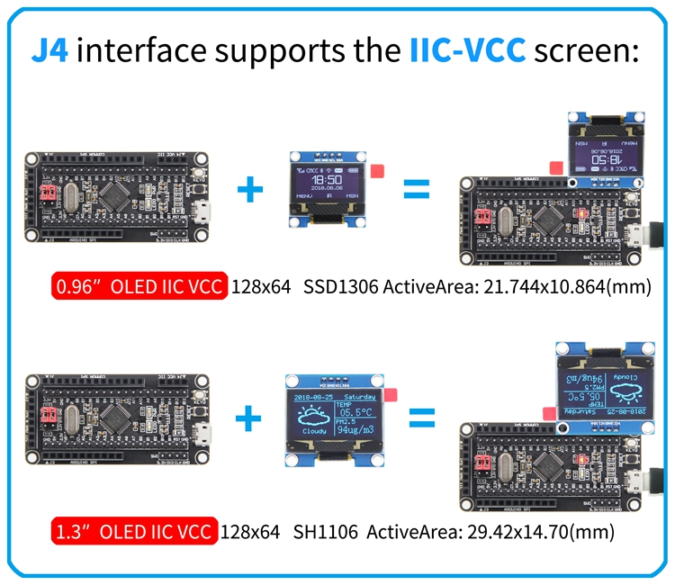
| | |J4 | ||
| | |Connect to the '''IIC-VCC''' display module | ||
|- | |- | ||
|⑤ | |⑤ | ||
| | |SWD | ||
| | |For SWD download and emulation | ||
|- | |- | ||
|⑥ | |⑥ | ||
| | |USB interface | ||
| | |Used for USB communication and power supply | ||
|- | |- | ||
|⑦ | |⑦ | ||
| | |Reset button | ||
| | |Reset development board | ||
|- | |- | ||
|⑧ | |⑧ | ||
| | |KEY0 | ||
| | |For standby wake up or program button function design | ||
|- | |- | ||
|⑨ | |⑨ | ||
|BT0/ | |BT0/BT1 | ||
| | |Used to select the startup mode after the development board is reset | ||
|- | |- | ||
|⑩ | |⑩ | ||
|STM32F103C8T6 | |STM32F103C8T6 | ||
| | |Main chip, main frequency: 72MHz, internal FLASH: 64KB, internal SRAM: 20KB, support RTC, interrupt, PWM, DMA and other functions | ||
|- | |- | ||
|⑪ | |⑪ | ||
| | |Power light | ||
| | |Red LED light is used to indicate whether the development board is normally powered | ||
|- | |- | ||
|⑫ | |⑫ | ||
| | |LED0 | ||
| | |Blue LED light, used to indicate the running status of the program and DIY program lighting effect design | ||
|- | |- | ||
|⑬,⑭ | |⑬,⑭ | ||
| | |IO expand | ||
| | |It is used to connect various peripherals to facilitate project development | ||
|- | |- | ||
|⑮ | |⑮ | ||
| | |Power stabilized IC | ||
| | |5V in,3.3V out | ||
|- | |- | ||
|⑯ | |⑯ | ||
| | |Self restoring fuse | ||
| | |Ensure the safety of the circuit in case of short circuit or other fault | ||
|} | |} | ||
==<font color="blue">How to connect LCD screen</font> == | ==<font color="blue">How to connect LCD screen</font> == | ||
[[File:开发板STM32F103C8T6-Commom-SPI- | [[File:开发板STM32F103C8T6-Commom-SPI-EN.jpg|750px]] | ||
[[File:开发板STM32F103C8T6-IIC-GND- | [[File:开发板STM32F103C8T6-IIC-GND-EN.jpg|750px]] | ||
[[File:开发板STM32F103C8T6-IPS- | [[File:开发板STM32F103C8T6-30-IPS-3-EN.jpg|750px]] | ||
[[File:开发板STM32F103C8T6-Arduino- | [[File:开发板STM32F103C8T6-Arduino-EN.jpg|750px]] | ||
[[File:开发板STM32F103C8T6-IIC-VCC- | [[File:开发板STM32F103C8T6-IIC-VCC-EN.jpg|750px]] | ||
==<font color="blue">Program Download</font> == | ==<font color="blue">Program Download</font> == | ||
* [http://www.lcdwiki.com/res/Program/Development_Board/STM32/STM32F103C8T6%E6%9C%80%E5%B0%8F%E7%B3%BB%E7%BB%9F%E6%9D%BF%E8%B5%84%E6%96%99%E5%8C%85.zip '''STM32F103C8T6最小系统板配套资料包'''] | * [http://www.lcdwiki.com/res/Program/Development_Board/STM32/STM32F103C8T6%E6%9C%80%E5%B0%8F%E7%B3%BB%E7%BB%9F%E6%9D%BF%E8%B5%84%E6%96%99%E5%8C%85.zip '''STM32F103C8T6最小系统板配套资料包'''] | ||
* [http://www.lcdwiki.com/res/STM3202/STM32F103C8T6%E6%9C%80%E5%B0%8F%E7%B3%BB%E7%BB%9F%E6%9D%BF%E7%9B%B4%E6%8F%92%E6%A8%A1%E5%9D%97%E6%B5%8B%E8%AF%95%E7%A8%8B%E5%BA%8F.zip '''STM32F103C8T6最小系统板直插模块测试程序'''] | |||
==<font color="blue">Product Documentation</font> == | ==<font color="blue">Product Documentation</font> == | ||
| Line 119: | Line 121: | ||
* [http://www.lcdwiki.com/res/software/FLYMCU.zip '''FLYMCU.zip'''] | * [http://www.lcdwiki.com/res/software/FLYMCU.zip '''FLYMCU.zip'''] | ||
* [http://www.lcdwiki.com/res/software/XCOM.zip '''XCOM.zip'''] | * [http://www.lcdwiki.com/res/software/XCOM.zip '''XCOM.zip'''] | ||
* [http://www.lcdwiki.com/res/software/PCtoLCD2002.zip '''PCtoLCD2002'''] | |||
* [http://www.lcdwiki.com/res/software/Image2Lcd.zip '''Image2Lcd'''] | |||
[[#top|BACK TO TOP]] | [[#top|BACK TO TOP]] | ||
Latest revision as of 15:44, 3 September 2021
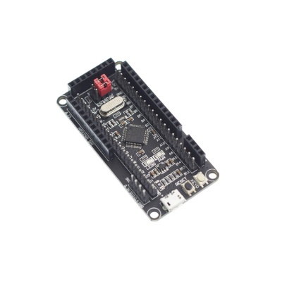
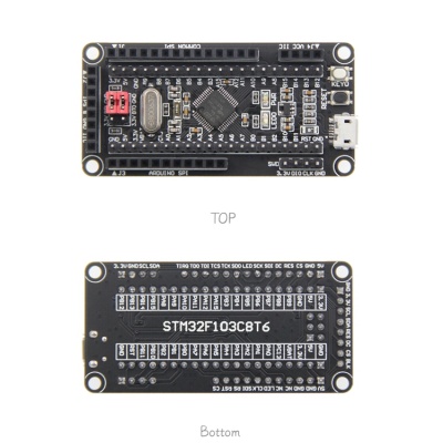
Product Picture
Product Description
- CPU: STM32F103C8T6, main frequency: 72MHz, internal FLASH: 64KB, internal SRAM: 20KB
- Small and delicate appearance, convenient for various DIY projects
- Support SWD and serial download, easy to debug
- Support SPI interface and IIC interface display module direct insertion
- Extended GPIO port for easy connection to various peripherals
- Rich development resources, easy to learn, easy to get started
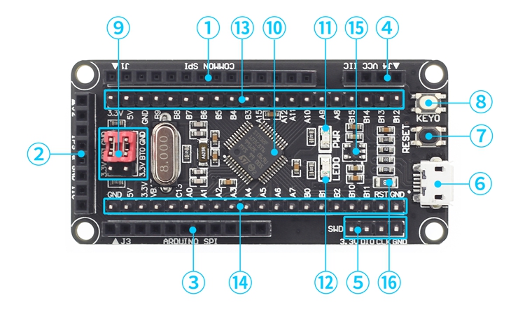
Product Parameters
| Serial number | Name | Description |
| ① | J1 | Connect to the Common-SPI display module |
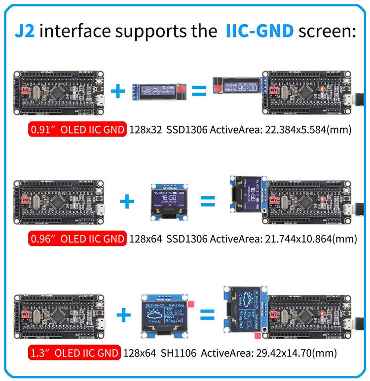
| ② | J2 | Connect to the Common-SPI/IPS display module |
| ③ | J3 | Connect to the Arduino-SPI display module |
| ④ | J4 | Connect to the IIC-VCC display module |
| ⑤ | SWD | For SWD download and emulation |
| ⑥ | USB interface | Used for USB communication and power supply |
| ⑦ | Reset button | Reset development board |
| ⑧ | KEY0 | For standby wake up or program button function design |
| ⑨ | BT0/BT1 | Used to select the startup mode after the development board is reset |
| ⑩ | STM32F103C8T6 | Main chip, main frequency: 72MHz, internal FLASH: 64KB, internal SRAM: 20KB, support RTC, interrupt, PWM, DMA and other functions |
| ⑪ | Power light | Red LED light is used to indicate whether the development board is normally powered |
| ⑫ | LED0 | Blue LED light, used to indicate the running status of the program and DIY program lighting effect design |
| ⑬,⑭ | IO expand | It is used to connect various peripherals to facilitate project development |
| ⑮ | Power stabilized IC | 5V in,3.3V out |
| ⑯ | Self restoring fuse | Ensure the safety of the circuit in case of short circuit or other fault |
How to connect LCD screen
Program Download
Product Documentation
- STM32F103C8T6最小系统板用户手册
- STM32F103C8T6最小系统板尺寸图
- STM32F103C8T6最小系统板原理图
- STM32F103C8T6最小系统板IO资源分配表
- STM32F103C8T6最小系统板原理图库
- STM32F103C8T6最小系统板PCB封装库
- STM32F103C8T6数据手册

