More actions
| (28 intermediate revisions by one other user not shown) | |||
| Line 7: | Line 7: | ||
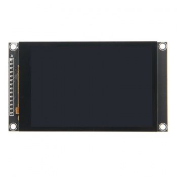
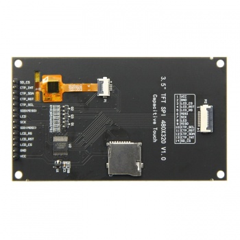
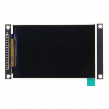
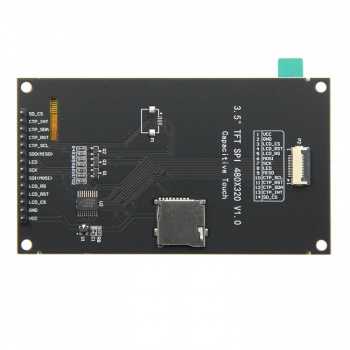
==<font color="blue">Product Picture</font> == | ==<font color="blue">Product Picture</font> == | ||
[[File:MSP3526- | [[File:MSP3526-2.jpg|350px]][[File:MSP3526-3.jpg|350px]][[File:MSP3525-1.jpg|350px]][[File:MSP3525-2.jpg|350px]] | ||
==<font color="blue">Product Description</font> == | ==<font color="blue">Product Description</font> == | ||
*3. | *3.5inch color screen with 320x480 resolution of 65K colors and rich display colors | ||
* | *The upgrade adopts IPS full view panel, with good visual angle | ||
* | *On board level conversion circuit, compatible with 5V and 3.3V MCU | ||
* | *Adopting a 4-wire SPI serial bus to save I/O pins | ||
* | *Optional capacitive touch/no touch function for modules | ||
* | *Module input supports 2.54 pin interface and FPC extension interface | ||
* | *Equipped with micro TF card slot for easy storage expansion | ||
*Provide rich example learning programs (ESP32/STM32/Arduino UNO&Mage2560/C51/CH32) | |||
* | *Provide low-level driver technical support, and update WIKI information online | ||
* | *Multiple tests for module aging can meet military level standards, supporting long-term stable work | ||
==<font color="blue"> | ==<font color="blue">Product Parameters</font> == | ||
{| class="wikitable" border="1" style="width: | {| class="wikitable" border="1" style="width: 600px; background-color: white;" | ||
| align="center" | | | align="center" |'''Name''' | ||
| align="center" | | | align="center" |'''Parameter''' | ||
|- | |- | ||
| colspan="2" align="center" | | | colspan="2" align="center" |'''LCD Parameters''' | ||
|- | |- | ||
| align="center" | | | align="center" |Screen Size | ||
| align="center" |3.5 inch | | align="center" |3.5 inch | ||
|- | |- | ||
| align="center" | | | align="center" |Screen Type | ||
| align="center" |IPS | | align="center" |IPS | ||
|- | |- | ||
| align="center" | | | align="center" |Resolution | ||
| align="center" |320xRGBx480 (pixels) | | align="center" |320xRGBx480 (pixels) | ||
|- | |- | ||
| align="center" | | | align="center" |Active Area (AA area) | ||
| align="center" |48.96(W)x73.44(H)(mm) | | align="center" |48.96(W)x73.44(H)(mm) | ||
|- | |- | ||
| align="center" | | | align="center" |Number of Colors(Max) | ||
| align="center" |16.7M | | align="center" |16.7M | ||
|- | |- | ||
| align="center" | | | align="center" |Driver IC | ||
| align="center" |ST7796U | | align="center" |ST7796U | ||
|- | |- | ||
| align="center" | | | align="center" |Display Interface | ||
| align="center" |4-Line SPI | | align="center" |4-Line SPI | ||
|- | |- | ||
| align="center" | | | align="center" |Pixel Size | ||
| align="center" |0.153(H)x0.153(mm) | | align="center" |0.153(H)x0.153(mm) | ||
|- | |- | ||
| align="center" | | | align="center" |View Angle | ||
| align="center" |ALL 0’CLOCK | | align="center" |ALL 0’CLOCK | ||
|- | |- | ||
| align="center" | | | align="center" |Brightness(TYP) | ||
| align="center" |300(cd/m<sup>2</sup>) | | align="center" |300(cd/m<sup>2</sup>) | ||
|- | |- | ||
| align="center" | | | align="center" |Backlight Type | ||
| align="center" |White LED*6 | | align="center" |White LED*6 | ||
|- | |- | ||
| align="center" | | | align="center" |Operation Temperature | ||
| align="center" | -10~50(℃) | | align="center" | -10~50(℃) | ||
|- | |- | ||
| align="center" | | | align="center" |Storage Temperature | ||
| align="center" | -20~60(℃) | | align="center" | -20~60(℃) | ||
|- | |- | ||
| colspan="2" align="center" | | | colspan="2" align="center" |'''Touch Screen Parameters''' | ||
|- | |- | ||
| align="center" | | | align="center" |Touch Active Area | ||
| align="center" |3.5 inch | | align="center" |3.5 inch | ||
|- | |- | ||
| align="center" | | | align="center" |Touch Screen Type | ||
| align="center" | | | align="center" |Capacitive Touch Screen | ||
|- | |- | ||
| align="center" | | | align="center" |Touch Screen Resolution | ||
| align="center" |320x480(pixels) | | align="center" |320x480(pixels) | ||
|- | |- | ||
| align="center" | | | align="center" |Driver IC | ||
| align="center" |FT6336U | | align="center" |FT6336U | ||
|- | |- | ||
| align="center" | | | align="center" |Touch Screen Visual Area | ||
| align="center" |49.56(w)x74.04(H)(mm) | | align="center" |49.56(w)x74.04(H)(mm) | ||
|- | |- | ||
| align="center" | | | align="center" |Communication Interface | ||
| align="center" |IIC | | align="center" |IIC | ||
|- | |- | ||
| align="center" | | | align="center" |Operation Temperature | ||
| align="center" | -20~70(℃) | | align="center" | -20~70(℃) | ||
|- | |- | ||
| align="center" | | | align="center" |Storage Temperature | ||
| align="center" | -30~80(℃) | | align="center" | -30~80(℃) | ||
|- | |- | ||
| colspan="2" align="center" | | | colspan="2" align="center" |'''Size Parameters''' | ||
|- | |- | ||
| align="center" | | | align="center" |TFT Outline Size | ||
| align="center" |55.50±0.2(W)x84.96±0.2(H)x2.5±0.1(D)(mm)( | | align="center" |55.50±0.2(W)x84.96±0.2(H)x2.5±0.1(D)(mm)(Excluding cables and adhesive backing) | ||
|- | |- | ||
| align="center" | | | align="center" |Touch Screen Outline Size | ||
| align="center" |55.50±0.2(W)x84.96±0.2(H)x0.8 (D)(mm)( | | align="center" |55.50±0.2(W)x84.96±0.2(H)x0.8 (D)(mm)(Excluding cables and adhesive backing) | ||
|- | |- | ||
| align="center" | | | align="center" |Module Outline Size | ||
| align="center" | | | align="center" |Have Touch Screen:55.5(W)x98.0(H)x12.98(D)(mm)(including Pin Header) | ||
NO Touch Screen:55.5(W)x98.0(H)x14.28(D)(mm)(including Pin Header) | |||
|- | |- | ||
| colspan="2" align="center" | | | colspan="2" align="center" |'''Electrical Parameters''' | ||
|- | |- | ||
| align="center" | | | align="center" |Working Voltage | ||
| align="center" |5.0 V | | align="center" |5.0 V | ||
|- | |- | ||
| align="center" | | | align="center" |Backlight Current | ||
| align="center" |95 mA | | align="center" |95 mA | ||
|- | |- | ||
| align="center" | | | align="center" |Power | ||
| align="center" |0.5 W | | align="center" |0.5 W | ||
|- | |- | ||
| colspan="2" align="center" | | | colspan="2" align="center" |'''Other Parameters''' | ||
|- | |- | ||
| align="center" |SKU | | align="center" |SKU | ||
| align="center" | | | align="center" |NO Touch Screen : MSP3525 | ||
Have Touch Screen : MSP3526 | |||
|- | |||
| align="center" |Interface | |||
| align="center" |14P 2.54mm spacing Header and 0.5mm spacing FPC seat | |||
|- | |||
| align="center" |Weight(including package) | |||
| align="center" |MSP3525: 73g | |||
MSP3526: 82g | |||
|} | |||
==<font color="blue">Interface Definition</font> == | |||
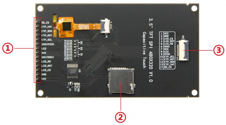
[[File:MSP3526-4.jpg|750px]] | |||
*'''Interface Function Description''' | |||
{| class="wikitable" border="1" style="width: 600px; background-color: white;" | |||
| align="center" |'''Number''' | |||
| align="center" |'''Interface''' | |||
| align="center" |'''Function Description''' | |||
|- | |- | ||
| align="center" | | | align="center" |'''①''' | ||
| align="center" | | | align="center" |'''14 Pin Header''' | ||
|2.54mm spacing row pins, module signal input pins | |||
|- | |- | ||
| align="center" | | | align="center" |'''②''' | ||
| align="center" | | | align="center" |'''Micro SD Slot''' | ||
|Insert a Micro SD card to expand storage space, such as storing big data content such as fonts and images | |||
|- | |||
| align="center" |'''③''' | |||
| align="center" |'''14P FPC''' | |||
|0.5mm FPC terminal, used for module signal input with the same function as ① | |||
|} | |} | ||
*'''Pin Function Description''' | |||
{| class="wikitable" border="1" style="width: 600px; background-color: white;" | {| class="wikitable" border="1" style="width: 600px; background-color: white;" | ||
| align="center" | | | align="center" |'''Number''' | ||
| align="center" | | | align="center" |'''Pin Label''' | ||
| align="center" | | | align="center" |Description | ||
|- | |- | ||
| align="center" |1 | | align="center" |1 | ||
| align="center" |VCC | | align="center" |'''VCC''' | ||
| | |Power positive | ||
|- | |- | ||
| align="center" |2 | | align="center" |2 | ||
| align="center" |GND | | align="center" |'''GND''' | ||
| | |Power ground | ||
|- | |- | ||
| align="center" |3 | | align="center" |3 | ||
| align="center" |LCD_CS | | align="center" |'''LCD_CS''' | ||
| | |LCD selection control signal, Low level active | ||
|- | |- | ||
| align="center" |4 | | align="center" |4 | ||
| align="center" |LCD_RST | | align="center" |'''LCD_RST''' | ||
| | |LCD reset control signal, Low level reset | ||
|- | |- | ||
| align="center" |5 | | align="center" |5 | ||
| align="center" |LCD_RS | | align="center" |'''LCD_RS''' | ||
| | |LCD command / data selection control signal | ||
High level: data, low level: command | |||
|- | |- | ||
| align="center" |6 | | align="center" |6 | ||
| align="center" |SDI(MOSI) | | align="center" |'''SDI(MOSI)''' | ||
| | |SPI bus write data signal(SD card and LCD screen used together) | ||
|- | |- | ||
| align="center" |7 | | align="center" |7 | ||
| align="center" |SCK | | align="center" |'''SCK''' | ||
| | |SPI bus clock signal(SD card and LCD screen used together) | ||
|- | |- | ||
| align="center" |8 | | align="center" |8 | ||
| align="center" |LED | | align="center" |'''LED''' | ||
| | |LCD backlight control signal (If you need control, please connect the pins. If you don't need control, you can skip it) | ||
|- | |- | ||
| align="center" |9 | | align="center" |9 | ||
| align="center" |SDO(MISO) | | align="center" |'''SDO(MISO)''' | ||
| | |SPI bus read data signal (SD card and LCD screen used together) | ||
|- | |- | ||
| align="center" |10 | | align="center" |10 | ||
| align="center" |CTP_SCL | | align="center" |'''CTP_SCL''' | ||
| | |Capacitive touch screen IIC bus clock signal (modules without touch screens do not need to be connected) | ||
|- | |- | ||
| align="center" |11 | | align="center" |11 | ||
| align="center" |CTP_RST | | align="center" |'''CTP_RST''' | ||
| | |Capacitor touch screen reset control signal, low-level reset (modules without touch screens do not need to be connected) | ||
|- | |- | ||
| align="center" |12 | | align="center" |12 | ||
| align="center" |CTP_SDA | | align="center" |'''CTP_SDA''' | ||
| | |Capacitive touch screen IIC bus data signal (modules without touch screens do not need to be connected) | ||
|- | |- | ||
| align="center" |13 | | align="center" |13 | ||
| align="center" |CTP_INT | | align="center" |'''CTP_INT''' | ||
| | |Capacitor touch screen IIC bus touch interrupt signal, when generating touch, input low level to the main control (modules without touch screens do not need to be connected) | ||
|- | |- | ||
| align="center" |14 | | align="center" |14 | ||
| align="center" |SD_CS | | align="center" |'''SD_CS''' | ||
| | |SD card selection control signal, low level active (without SD card function, can be disconnected) | ||
|- | |- | ||
|} | |} | ||
==<font color="blue"> | ==<font color="blue">Product Documentation</font> == | ||
* [http://www.lcdwiki.com/res/MSP3525_MSP3526/3. | * [http://www.lcdwiki.com/res/MSP3525_MSP3526/MSP3525_MSP3526_Specification_EN_V1.0.pdf '''3.5inch IPS SPI Module Specification'''] | ||
* [http://www.lcdwiki.com/res/MSP3525_MSP3526/QD3525-Specifications-A.pdf '''3. | * [http://www.lcdwiki.com/res/MSP3525_MSP3526/3.5inch_SPI_Module_MSP3525_MSP3526_User_Manual_EN.pdf '''3.5inch IPS SPI Module User Manual'''] | ||
* [http://www.lcdwiki.com/res/MSP3525_MSP3526/3. | * [http://www.lcdwiki.com/res/MSP3525_MSP3526/ST7796_Init.txt '''ST7796 initialization'''] | ||
* [http://www.lcdwiki.com/res/MSP3525_MSP3526/3. | * [http://www.lcdwiki.com/res/MSP3525_MSP3526/QD3525-Specifications-A.pdf '''3.5inch IPS LCD Specifications'''] | ||
* [http://www.lcdwiki.com/res/MSP3525_MSP3526/3. | * [http://www.lcdwiki.com/res/MSP3525_MSP3526/3.5inch_CTP_Module_FT6336U_Size.pdf '''3.5inch Capacitive Touch Screen Size Picture'''] | ||
* [http://www.lcdwiki.com/res/MSP3525_MSP3526/3. | * [http://www.lcdwiki.com/res/MSP3525_MSP3526/3.5inch_SPI_Module_MSP3526_Size.pdf '''3.5inch IPS SPI Module with Touch Screen Size Picture'''] | ||
* [http://www.lcdwiki.com/res/MSP3525_MSP3526/Altium_3.5inch_48pin_QD3525_Package_library.zip '''3. | * [http://www.lcdwiki.com/res/MSP3525_MSP3526/3.5inch_SPI_Module_MSP3525_Size.pdf '''3.5inch IPS SPI Module without Touch Screen Size Picture'''] | ||
* [http://www.lcdwiki.com/res/MSP3525_MSP3526/ST7796S-Sitronix.pdf ''' | * [http://www.lcdwiki.com/res/MSP3525_MSP3526/3.5inch_SPI_Module_MSP3525_MSP3526_Schematic.pdf '''3.5inch IPS SPI Module Schematic'''] | ||
* [http://www.lcdwiki.com/res/MSP3525_MSP3526/DFT6336UDataSheetV1.1.pdf ''' | * [http://www.lcdwiki.com/res/MSP3525_MSP3526/Altium_3.5inch_48pin_QD3525_Package_library.zip '''3.5inch IPS SPI Module screen Schematic and PCB package library'''] | ||
* [http://www.lcdwiki.com/res/MSP3525_MSP3526/FT6336U_Register.xlsx ''' | * [http://www.lcdwiki.com/res/MSP3525_MSP3526/ST7796S-Sitronix.pdf '''LCD Driver IC ST7796S Data sheet'''] | ||
* [http://www.lcdwiki.com/res/MSP3525_MSP3526/DFT6336UDataSheetV1.1.pdf '''Touch Screen Driver IC FT6336U Data sheet'''] | |||
* [http://www.lcdwiki.com/res/MSP3525_MSP3526/FT6336U_Register.xlsx '''Touch Screen Driver IC FT6336U Register Table'''] | |||
==<font color="blue"> | ==<font color="blue">Program Download</font> == | ||
* [http://www.lcdwiki.com/res/Program/ | * [http://www.lcdwiki.com/res/Program/CTP_SPI/3.5inch/SPI_ST7796_MSP3525_MSP3526_V1.0/3.5inch_SPI_Module_ST7796_MSP3525_MSP3526_V1.0.zip '''3.5inch IPS SPI Module MSP3525_MSP3526 Package'''] | ||
==<font color="blue"> | ==<font color="blue">Reference Materials</font> == | ||
* [http://www.lcdwiki.com/res/MSP3525_MSP3526/3. | * [http://www.lcdwiki.com/res/MSP3525_MSP3526/3.5inch_SPI_MSP3525_MSP3526_C51_Demo_Instructions_EN.pdf '''3.5inch IPS SPI Module C51 Demo Instructions'''] | ||
* [http://www.lcdwiki.com/res/MSP3525_MSP3526/3. | * [http://www.lcdwiki.com/res/MSP3525_MSP3526/3.5inch_SPI_MSP3525_MSP3526_CH32_Demo_Instructions_EN.pdf '''3.5inch IPS SPI Module CH32 Demo Instructions'''] | ||
* [http://www.lcdwiki.com/res/MSP3525_MSP3526/3. | * [http://www.lcdwiki.com/res/MSP3525_MSP3526/3.5inch_SPI_MSP3525_MSP3526_ESP32_Demo_Instructions_EN.pdf '''3.5inch IPS SPI Module ESP32 Demo Instructions'''] | ||
* [http://www.lcdwiki.com/res/MSP3525_MSP3526/3. | * [http://www.lcdwiki.com/res/MSP3525_MSP3526/3.5inch_SPI_MSP3525_MSP3526_STM32_Demo_Instructions_EN.pdf '''3.5inch IPS SPI Module STM32 Demo Instructions'''] | ||
* [http://www.lcdwiki.com/res/MSP3525_MSP3526/3. | * [http://www.lcdwiki.com/res/MSP3525_MSP3526/3.5inch_SPI_MSP3525_MSP3526_UNO_Mega2560_Demo_Instructions_EN.pdf '''3.5inch IPS SPI Module UNO_Mega2560 Demo Instructions'''] | ||
* [http://www.lcdwiki.com/res/PublicFile/ | * [http://www.lcdwiki.com/res/PublicFile/Arduino_development_environment_construction_for_ESP32_EN.pdf '''Arduino development environment construction for ESP32'''] | ||
* [http://www.lcdwiki.com/res/PublicFile/ | * [http://www.lcdwiki.com/res/PublicFile/PCtoLCD2002_Use_Illustration_EN.pdf '''PCtoLCD2002 software use illustration'''] | ||
* [http://www.lcdwiki.com/res/PublicFile/ | * [http://www.lcdwiki.com/res/PublicFile/Image2Lcd_Use_Illustration_EN.pdf '''Image2Lcd software use illustration'''] | ||
* [http://www.lcdwiki.com/res/PublicFile/ | * [http://www.lcdwiki.com/res/PublicFile/Flash_Download_Operation_Instructions_EN.pdf '''flash_download_tool software use illustration(use for ESP32)'''] | ||
* [http://www.lcdwiki.com/ | * [http://www.lcdwiki.com/Chinese_and_English_display_modulo_settings '''Chinese and English display modulo settings'''] | ||
==<font color="blue"> | ==<font color="blue">Common Software</font> == | ||
* [http://www.lcdwiki.com/res/software/PCtoLCD2002.zip '''PCtoLCD2002'''] | * [http://www.lcdwiki.com/res/software/PCtoLCD2002.zip '''PCtoLCD2002'''] | ||
Latest revision as of 16:09, 19 July 2023
Product Picture
Product Description
- 3.5inch color screen with 320x480 resolution of 65K colors and rich display colors
- The upgrade adopts IPS full view panel, with good visual angle
- On board level conversion circuit, compatible with 5V and 3.3V MCU
- Adopting a 4-wire SPI serial bus to save I/O pins
- Optional capacitive touch/no touch function for modules
- Module input supports 2.54 pin interface and FPC extension interface
- Equipped with micro TF card slot for easy storage expansion
- Provide rich example learning programs (ESP32/STM32/Arduino UNO&Mage2560/C51/CH32)
- Provide low-level driver technical support, and update WIKI information online
- Multiple tests for module aging can meet military level standards, supporting long-term stable work
Product Parameters
| Name | Parameter |
| LCD Parameters | |
| Screen Size | 3.5 inch |
| Screen Type | IPS |
| Resolution | 320xRGBx480 (pixels) |
| Active Area (AA area) | 48.96(W)x73.44(H)(mm) |
| Number of Colors(Max) | 16.7M |
| Driver IC | ST7796U |
| Display Interface | 4-Line SPI |
| Pixel Size | 0.153(H)x0.153(mm) |
| View Angle | ALL 0’CLOCK |
| Brightness(TYP) | 300(cd/m2) |
| Backlight Type | White LED*6 |
| Operation Temperature | -10~50(℃) |
| Storage Temperature | -20~60(℃) |
| Touch Screen Parameters | |
| Touch Active Area | 3.5 inch |
| Touch Screen Type | Capacitive Touch Screen |
| Touch Screen Resolution | 320x480(pixels) |
| Driver IC | FT6336U |
| Touch Screen Visual Area | 49.56(w)x74.04(H)(mm) |
| Communication Interface | IIC |
| Operation Temperature | -20~70(℃) |
| Storage Temperature | -30~80(℃) |
| Size Parameters | |
| TFT Outline Size | 55.50±0.2(W)x84.96±0.2(H)x2.5±0.1(D)(mm)(Excluding cables and adhesive backing) |
| Touch Screen Outline Size | 55.50±0.2(W)x84.96±0.2(H)x0.8 (D)(mm)(Excluding cables and adhesive backing) |
| Module Outline Size | Have Touch Screen:55.5(W)x98.0(H)x12.98(D)(mm)(including Pin Header)
NO Touch Screen:55.5(W)x98.0(H)x14.28(D)(mm)(including Pin Header) |
| Electrical Parameters | |
| Working Voltage | 5.0 V |
| Backlight Current | 95 mA |
| Power | 0.5 W |
| Other Parameters | |
| SKU | NO Touch Screen : MSP3525
Have Touch Screen : MSP3526 |
| Interface | 14P 2.54mm spacing Header and 0.5mm spacing FPC seat |
| Weight(including package) | MSP3525: 73g
MSP3526: 82g |
Interface Definition
- Interface Function Description
| Number | Interface | Function Description |
| ① | 14 Pin Header | 2.54mm spacing row pins, module signal input pins |
| ② | Micro SD Slot | Insert a Micro SD card to expand storage space, such as storing big data content such as fonts and images |
| ③ | 14P FPC | 0.5mm FPC terminal, used for module signal input with the same function as ① |
- Pin Function Description
| Number | Pin Label | Description |
| 1 | VCC | Power positive |
| 2 | GND | Power ground |
| 3 | LCD_CS | LCD selection control signal, Low level active |
| 4 | LCD_RST | LCD reset control signal, Low level reset |
| 5 | LCD_RS | LCD command / data selection control signal
High level: data, low level: command |
| 6 | SDI(MOSI) | SPI bus write data signal(SD card and LCD screen used together) |
| 7 | SCK | SPI bus clock signal(SD card and LCD screen used together) |
| 8 | LED | LCD backlight control signal (If you need control, please connect the pins. If you don't need control, you can skip it) |
| 9 | SDO(MISO) | SPI bus read data signal (SD card and LCD screen used together) |
| 10 | CTP_SCL | Capacitive touch screen IIC bus clock signal (modules without touch screens do not need to be connected) |
| 11 | CTP_RST | Capacitor touch screen reset control signal, low-level reset (modules without touch screens do not need to be connected) |
| 12 | CTP_SDA | Capacitive touch screen IIC bus data signal (modules without touch screens do not need to be connected) |
| 13 | CTP_INT | Capacitor touch screen IIC bus touch interrupt signal, when generating touch, input low level to the main control (modules without touch screens do not need to be connected) |
| 14 | SD_CS | SD card selection control signal, low level active (without SD card function, can be disconnected) |
Product Documentation
- 3.5inch IPS SPI Module Specification
- 3.5inch IPS SPI Module User Manual
- ST7796 initialization
- 3.5inch IPS LCD Specifications
- 3.5inch Capacitive Touch Screen Size Picture
- 3.5inch IPS SPI Module with Touch Screen Size Picture
- 3.5inch IPS SPI Module without Touch Screen Size Picture
- 3.5inch IPS SPI Module Schematic
- 3.5inch IPS SPI Module screen Schematic and PCB package library
- LCD Driver IC ST7796S Data sheet
- Touch Screen Driver IC FT6336U Data sheet
- Touch Screen Driver IC FT6336U Register Table
Program Download
Reference Materials
- 3.5inch IPS SPI Module C51 Demo Instructions
- 3.5inch IPS SPI Module CH32 Demo Instructions
- 3.5inch IPS SPI Module ESP32 Demo Instructions
- 3.5inch IPS SPI Module STM32 Demo Instructions
- 3.5inch IPS SPI Module UNO_Mega2560 Demo Instructions
- Arduino development environment construction for ESP32
- PCtoLCD2002 software use illustration
- Image2Lcd software use illustration
- flash_download_tool software use illustration(use for ESP32)
- Chinese and English display modulo settings

