More actions
| (5 intermediate revisions by the same user not shown) | |||
| Line 48: | Line 48: | ||
|- | |- | ||
| align="center" |Display Interface | | align="center" |Display Interface | ||
| align="center" |IIC | | align="center" |4-Wire SPI(default)/IIC | ||
|- | |- | ||
| align="center" |Pixel Size | | align="center" |Pixel Size | ||
| Line 87: | Line 87: | ||
|- | |- | ||
| align="center" |SKU | | align="center" |SKU | ||
| align="center" | | | align="center" |MSP242W (White)/MSP242B (Blue)/MSP242Y (Yellow) | ||
|- | |- | ||
| align="center" |Interface | | align="center" |Interface | ||
| align="center" | | | align="center" |7Pin 2.54mm Header | ||
|- | |- | ||
| align="center" |Weight(including package) | | align="center" |Weight(including package) | ||
| align="center" | | | align="center" |25g | ||
|} | |} | ||
| Line 107: | Line 107: | ||
|- | |- | ||
| align="center" |'''①''' | | align="center" |'''①''' | ||
| align="center" |''' | | align="center" |'''7 Pin Header''' | ||
|2.54mm spacing row pins, module signal input pins | |2.54mm spacing row pins, module signal input pins | ||
|- | |- | ||
| align="center" |'''②''' | | align="center" |'''②''' | ||
| align="center" |''' | | align="center" |'''Communication Interface Switching Resistor''' | ||
| | |If only R5 resistors are welded, use SPI communication interface (default) | ||
If only R4 and R9 resistors are welded, use the IIC communication interface | |||
|- | |||
| align="center" |'''③''' | |||
| align="center" |'''CS Pin Grounding Resistance''' | |||
|R8 resistors are not welded by default. If the R8 resistor is welded, the CS pin can be suspended | |||
|} | |} | ||
| Line 134: | Line 138: | ||
| align="center" |3 | | align="center" |3 | ||
| align="center" |'''SCL''' | | align="center" |'''SCL''' | ||
|IIC bus clock signal | |Using SPI interface: SPI bus clock signal | ||
Using IIC interface: IIC bus clock signal | |||
|- | |- | ||
| align="center" |4 | | align="center" |4 | ||
| align="center" |'''SDA''' | | align="center" |'''SDA''' | ||
|IIC bus data signal | |Using SPI interface: SPI bus to write data signals | ||
Using IIC interface: IIC bus data signal | |||
|- | |- | ||
| align="center" |5 | | align="center" |5 | ||
| align="center" |'''RES''' | | align="center" |'''RES''' | ||
| | |OLED screen reset control signal, low-level reset (if using IIC interface, this pin can be left unchecked and connected to 3.3V high-level) | ||
|- | |||
| align="center" |6 | |||
| align="center" |'''DC''' | |||
|Using SPI interface: OLED screen command/data selection control signal (high level: data, low level: command) | |||
Using IIC interface: The IIC bus selects signals from the device address (high level: 0x7A, low level: 0x78, which can be controlled by the master GPIO or connected to 3.3V high level or GND) | |||
|- | |||
| align="center" |7 | |||
| align="center" |'''CS''' | |||
|OLED screen chip selection control signal, effective at low level (if R8 resistor is soldered, this pin can be suspended. If R8 resistor is not soldered, when using IIC interface, this pin must be connected to low level, which can be controlled by master GPIO or GND) | |||
|- | |- | ||
|} | |} | ||
| Line 148: | Line 166: | ||
==<font color="blue">Product Documentation</font> == | ==<font color="blue">Product Documentation</font> == | ||
* [http://www.lcdwiki.com/res/ | * [http://www.lcdwiki.com/res/MSP242X/MSP242X_Specification_EN_V1.0.pdf '''2.42inch OLED SPI_IIC Module Specification'''] | ||
* [http://www.lcdwiki.com/res/ | * [http://www.lcdwiki.com/res/MSP242X/2.42inch_OLED_SPI_IIC_Module_MSP242X_User_Manual_EN.pdf '''2.42inch OLED SPI_IIC Module User Manual'''] | ||
* [http://www.lcdwiki.com/res/ | * [http://www.lcdwiki.com/res/MSP242X/2.42inch_SSD1309_Init.txt '''2.42inch OLED SSD1309 initialization'''] | ||
* [http://www.lcdwiki.com/res/ | * [http://www.lcdwiki.com/res/MSP242X/OLED242W_SPEC.pdf '''2.42inch OLED Screen Specifications(White)'''] | ||
* [http://www.lcdwiki.com/res/ | * [http://www.lcdwiki.com/res/MSP242X/OLED242B_SPEC.pdf '''2.42inch OLED Screen Specifications(Blue)'''] | ||
* [http://www.lcdwiki.com/res/ | * [http://www.lcdwiki.com/res/MSP242X/OLED242Y_SPEC.pdf '''2.42inch OLED Screen Specifications(Yellow)'''] | ||
* [http://www.lcdwiki.com/res/ | * [http://www.lcdwiki.com/res/MSP242X/2.42inch_SPI_IIC_Module_MSP242X_Size.pdf '''2.42inch OLED SPI_IIC Module Size Picture'''] | ||
* [http://www.lcdwiki.com/res/ | * [http://www.lcdwiki.com/res/MSP242X/2.42inch_SPI_IIC_Module_MSP242X_Schematic.pdf '''2.42inch OLED SPI_IIC Module Schematic'''] | ||
* [http://www.lcdwiki.com/res/ | * [http://www.lcdwiki.com/res/MSP242X/Altium_2.42inch_OLED_24pin_OLED242X_Package_library.zip '''2.42inch OLED Screen Schematic and PCB package library'''] | ||
* [http://www.lcdwiki.com/res/ | * [http://www.lcdwiki.com/res/MSP242X/SSD1309.pdf '''OLED Screen Driver IC SSD1309 Data sheet'''] | ||
==<font color="blue">Program Download</font> == | ==<font color="blue">Program Download</font> == | ||
* [http://www.lcdwiki.com/res/Program/OLED/2.42inch/ | * [http://www.lcdwiki.com/res/Program/OLED/2.42inch/SPI_IIC_SSD1309_MSP242X_V1.0/2.42inch_OLED_SSD1309_SPI_IIC_Module_MSP242X_V1.0.zip '''2.42inch OLED SPI_IIC Module MC242GX Package'''] | ||
==<font color="blue">Reference Materials</font> == | ==<font color="blue">Reference Materials</font> == | ||
* [http://www.lcdwiki.com/res/ | * [http://www.lcdwiki.com/res/MSP242X/2.42inch_OLED_SPI_IIC_MSP242X_C51_Demo_Instructions_EN.pdf '''2.42inch OLED SPI_IIC Module C51 Demo Instructions'''] | ||
* [http://www.lcdwiki.com/res/ | * [http://www.lcdwiki.com/res/MSP242X/2.42inch_OLED_SPI_IIC_MSP242X_CH32_Demo_Instructions_EN.pdf '''2.42inch OLED SPI_IIC Module CH32 Demo Instructions'''] | ||
* [http://www.lcdwiki.com/res/ | * [http://www.lcdwiki.com/res/MSP242X/2.42inch_OLED_SPI_IIC_MSP242X_ESP32_Demo_Instructions_EN.pdf '''2.42inch OLED SPI_IIC Module ESP32 Demo Instructions'''] | ||
* [http://www.lcdwiki.com/res/ | * [http://www.lcdwiki.com/res/MSP242X/2.42inch_OLED_SPI_IIC_MSP242X_STM32_Demo_Instructions_EN.pdf '''2.42inch OLED SPI_IIC Module STM32 Demo Instructions'''] | ||
* [http://www.lcdwiki.com/res/ | * [http://www.lcdwiki.com/res/MSP242X/2.42inch_OLED_SPI_IIC_MSP242X_UNO_Mega2560_Demo_Instructions_EN.pdf '''2.42inch OLED SPI_IIC Module UNO_Mega2560 Demo Instructions'''] | ||
* [http://www.lcdwiki.com/res/ | * [http://www.lcdwiki.com/res/MSP242X/2.42inch_OLED_SPI_IIC_MSP242X_RaspberryPi_Demo_Instructions_EN.pdf '''2.42inch OLED SPI_IIC Module RaspberryPi Demo Instructions'''] | ||
* [http://www.lcdwiki.com/res/PublicFile/Arduino_development_environment_construction_for_ESP32_EN.pdf '''Arduino development environment construction for ESP32'''] | * [http://www.lcdwiki.com/res/PublicFile/Arduino_development_environment_construction_for_ESP32_EN.pdf '''Arduino development environment construction for ESP32'''] | ||
* [http://www.lcdwiki.com/res/PublicFile/PCtoLCD2002_Use_Illustration_EN.pdf '''PCtoLCD2002 software use illustration'''] | * [http://www.lcdwiki.com/res/PublicFile/PCtoLCD2002_Use_Illustration_EN.pdf '''PCtoLCD2002 software use illustration'''] | ||
Latest revision as of 18:32, 15 August 2023
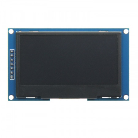
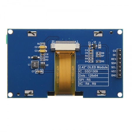
Product Picture
Product Description
- 2.42” OLED monochrome screen, equipped with three monochrome displays: white, yellow, and blue
- 128x64 resolution, clear display effect, high contrast
- Large viewing angle: greater than 160 ° (the screen with the largest viewing angle in the display screen)
- Wide voltage power supply (3V~5V), compatible with 3.3V and 5V logic levels, without the need for level conversion chips
- By default, 4-wire SPI serial bus is used, supporting switching to IIC bus
- Equipped with an iron frame, it can effectively protect the display screen
- Ultra low power consumption (much lower than TFT display screen)
- Provide rich example learning programs (ESP32/STM32/ Arduino/C51/CH32/RaspberryPi)
- Provide low-level driver technical support, and update WIKI information online
- Multiple tests for module aging can meet military level standards, supporting long-term stable work
Product Parameters
| Name | Parameter |
| Display Screen Parameters | |
| Screen Size | 2.42 inch |
| Screen Type | OLED |
| Resolution | 128x64 (pixels) |
| Active Area (AA area) | 55.01(W)x27.49(H)(mm) |
| Display Color | White/Blue/Yellow (Monochrome) |
| Driver IC | SSD1309 |
| Display Interface | 4-Wire SPI(default)/IIC |
| Pixel Size | 0.43(H)x0.43(V)(mm) |
| View Angle | ALL 0’CLOCK |
| Brightness(TYP) | 110(cd/m2) |
| Operation Temperature | -40~70(℃) |
| Storage Temperature | -40~85(℃) |
| Size Parameters | |
| OLED Outline Size | 60.5±0.2(W)x37.0±0.2(H)x2.0±0.1(D)(mm)(Excluding cables and adhesive backing) |
| Module Outline Size | 72.0(W)x43.0(H)x12.39(D)(mm)(including Pin Header) |
| Electrical Parameters | |
| Working Voltage | 5.0/3.3V |
| Working Current | 52 mA(Max) |
| Power | 0.26W(Max) |
| Other Parameters | |
| SKU | MSP242W (White)/MSP242B (Blue)/MSP242Y (Yellow) |
| Interface | 7Pin 2.54mm Header |
| Weight(including package) | 25g |
Interface Definition
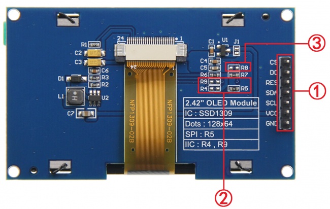
- Interface Function Description
| Number | Interface | Function Description |
| ① | 7 Pin Header | 2.54mm spacing row pins, module signal input pins |
| ② | Communication Interface Switching Resistor | If only R5 resistors are welded, use SPI communication interface (default)
If only R4 and R9 resistors are welded, use the IIC communication interface |
| ③ | CS Pin Grounding Resistance | R8 resistors are not welded by default. If the R8 resistor is welded, the CS pin can be suspended |
- Pin Function Description
| Number | Pin Label | Description |
| 1 | GND | OLED screen power supply ground |
| 2 | VCC | OLED screen power supply positive pole (connected to 5V/3.3V) |
| 3 | SCL | Using SPI interface: SPI bus clock signal
Using IIC interface: IIC bus clock signal |
| 4 | SDA | Using SPI interface: SPI bus to write data signals
Using IIC interface: IIC bus data signal |
| 5 | RES | OLED screen reset control signal, low-level reset (if using IIC interface, this pin can be left unchecked and connected to 3.3V high-level) |
| 6 | DC | Using SPI interface: OLED screen command/data selection control signal (high level: data, low level: command)
Using IIC interface: The IIC bus selects signals from the device address (high level: 0x7A, low level: 0x78, which can be controlled by the master GPIO or connected to 3.3V high level or GND) |
| 7 | CS | OLED screen chip selection control signal, effective at low level (if R8 resistor is soldered, this pin can be suspended. If R8 resistor is not soldered, when using IIC interface, this pin must be connected to low level, which can be controlled by master GPIO or GND) |
Product Documentation
- 2.42inch OLED SPI_IIC Module Specification
- 2.42inch OLED SPI_IIC Module User Manual
- 2.42inch OLED SSD1309 initialization
- 2.42inch OLED Screen Specifications(White)
- 2.42inch OLED Screen Specifications(Blue)
- 2.42inch OLED Screen Specifications(Yellow)
- 2.42inch OLED SPI_IIC Module Size Picture
- 2.42inch OLED SPI_IIC Module Schematic
- 2.42inch OLED Screen Schematic and PCB package library
- OLED Screen Driver IC SSD1309 Data sheet
Program Download
Reference Materials
- 2.42inch OLED SPI_IIC Module C51 Demo Instructions
- 2.42inch OLED SPI_IIC Module CH32 Demo Instructions
- 2.42inch OLED SPI_IIC Module ESP32 Demo Instructions
- 2.42inch OLED SPI_IIC Module STM32 Demo Instructions
- 2.42inch OLED SPI_IIC Module UNO_Mega2560 Demo Instructions
- 2.42inch OLED SPI_IIC Module RaspberryPi Demo Instructions
- Arduino development environment construction for ESP32
- PCtoLCD2002 software use illustration
- Image2Lcd software use illustration
- Chinese and English display modulo settings


