More actions
| (48 intermediate revisions by 2 users not shown) | |||
| Line 6: | Line 6: | ||
}} | }} | ||
== <font color="blue">Product | |||
== <font color="blue">Product Video</font> == | |||
{{#ev:youtube|8g5vvE-9KYE}} | |||
*[http://www.lcdwiki.com/Video_Presentation Related Video] | |||
== <font color="blue">Product Picture</font> == | |||
[[File:MAR2808-011.jpg|300px]] | |||
[[File:MAR2808-009.jpg|300px]] | [[File:MAR2808-009.jpg|300px]] | ||
==<font color="blue">Product | ==<font color="blue">Product Description</font> == | ||
* Supports development boards such as Arduino UNO and Mega2560 for plug-in use without wiring | |||
* 320X240 resolution, clear display, support for touch function | |||
* Support 16-bit RGB 65K color display, display rich colors | |||
* 8-bit parallel bus, faster than serial SPI refresh | |||
* On-board 5V/3.3V level shifting IC, compatible with 5V/3.3V operating voltage | |||
* Easy to expand the experiment with SD card slot | |||
* Provides an Arduino library with a rich sample program | |||
* Military-grade process standards, long-term stable work | |||
* Provide underlying driver technical support | |||
==<font color="blue">Product Parameters</font> == | |||
{| class="wikitable" border="1" style="width: 500px; background-color: white;" | {| class="wikitable" border="1" style="width: 500px; background-color: white;" | ||
| | | align="center" |Name | ||
| | | align="center" |Parameter | ||
|- | |- | ||
| | | align="center" |Display Color | ||
| | | align="center" |RGB 65K color | ||
|- | |- | ||
| | | align="center" |SKU | ||
| | | align="center" |MAR2808 | ||
|- | |- | ||
| | | align="center" |Screen Size | ||
| | | align="center" |2.8(inch) | ||
|- | |- | ||
| | | align="center" |Type | ||
| | | align="center" |TFT | ||
|- | |- | ||
| | | align="center" |Driver IC | ||
| | | align="center" |ILI9341 | ||
|- | |- | ||
| | | align="center" |Resolution | ||
| | | align="center" |320*240 (Pixel) | ||
|- | |- | ||
| | | align="center" |Module Interface | ||
| | | align="center" |8-bit parallel interface | ||
|- | |- | ||
| | | align="center" |Active Area | ||
| | | align="center" |43.2*57.6(mm) | ||
|- | |- | ||
| | | align="center" |Module PCB Size | ||
| | | align="center" |52.70*78.22(mm) | ||
|- | |- | ||
| | | align="center" |Operating Temperature | ||
| | | align="center" | -20℃~60℃ | ||
|- | |- | ||
| | | align="center" |Storage Temperature | ||
| | | align="center" | -30℃~70℃ | ||
|- | |- | ||
| | | align="center" |Operating Voltage | ||
| | | align="center" |5V/3.3V | ||
|- | |||
| align="center" |Power Consumption | |||
| align="center" |TBD | |||
|- | |||
| align="center" |Product Weight(Package containing) | |||
| align="center" |44(g) | |||
|} | |} | ||
==<font color="blue">Interface | ==<font color="blue">Interface Definition</font> == | ||
[[file:MAR2808- | [[file:MAR2808-037.jpg|left|500x500px]] | ||
{| class="wikitable" border="1" style="width: | {| class="wikitable" border="1" style="width: 550px; background-color: white;" | ||
|- | |- | ||
| align="center" | | | align="center" |Number | ||
| align="center" | | | align="center" |Pin Label | ||
| align="center" | | | align="center" |Pin Description | ||
|- | |- | ||
| align="center" |1 | | align="center" |1 | ||
| align="center" |LCD_RST | | align="center" |LCD_RST | ||
|LCD bus reset signal | |LCD bus reset signal, low level reset | ||
|- | |- | ||
| align="center" |2 | | align="center" |2 | ||
| align="center" |LCD_CS | | align="center" |LCD_CS | ||
|LCD bus chip select signal | |LCD bus chip select signal, low level enable | ||
|- | |- | ||
| align="center" |3 | | align="center" |3 | ||
| align="center" |LCD_RS | | align="center" |LCD_RS | ||
|LCD bus command/data | |LCD bus command / data selection signal, | ||
low level: command, high level: data | |||
|- | |- | ||
| align="center" |4 | | align="center" |4 | ||
| Line 95: | Line 107: | ||
| align="center" |6 | | align="center" |6 | ||
| align="center" |GND | | align="center" |GND | ||
| | |Power ground | ||
|- | |- | ||
| align="center" |7 | | align="center" |7 | ||
| Line 103: | Line 115: | ||
| align="center" |8 | | align="center" |8 | ||
| align="center" |3V3 | | align="center" |3V3 | ||
| | |3.3V power input, this pin can be disconnected | ||
|- | |- | ||
| align="center" |9 | | align="center" |9 | ||
| Line 139: | Line 151: | ||
| align="center" |17 | | align="center" |17 | ||
| align="center" |SD_SS | | align="center" |SD_SS | ||
|SD card SPI bus chip select signal | |SD card SPI bus chip select signal, low level enable | ||
|- | |- | ||
| align="center" |18 | | align="center" |18 | ||
| Line 154: | Line 166: | ||
|} | |} | ||
==<font color="blue"> | ==<font color="blue">Connect to Arduino</font> == | ||
{| class="FCK__ShowTableBorders" align="left" | |||
{| class=" | |||
|- | |- | ||
! | ![[file:MAR2808-038.jpg|无框|400x400px]] | ||
![[file:MAR2808-039.jpg|无框|400x400px]] | |||
! | |||
|- | |- | ||
| align="center" | | | align="center" | '''Arduino UNO direct insertion picture''' | ||
| align="center" | | | align="center" | '''Arduino Mega2560 direct insertion picture''' | ||
|} | |} | ||
<br clear="all"> | |||
==<font color="blue">How to use on Arduino</font> == | |||
*'''Step 1: Download the test program''' | |||
[[ | # Download the Arduino test program from the [[#Program Download|'''Program Download''']] column | ||
# For a description of the relevant test procedures, please refer to the test program documentation in the package | |||
*'''Step 2: Connect the Arduino development board''' | |||
# Plug the module directly into the Arduino development board ([[#Connect to Arduino| <font color="red"> '''Do not plug in?'''</font>]]) | |||
# After the module is plugged in, power on the Arduino board | |||
*'''Step 3: Copy the dependent library''' | |||
# Make sure the Arduino IDE is installed on your computer (if it is not installed: [https://www.arduino.cc/en/Main/Software '''Arduino IDE download URL''']) | |||
# After installing the Arduino IDE, you need to copy the dependent library to the Arduino project directory as follows: | |||
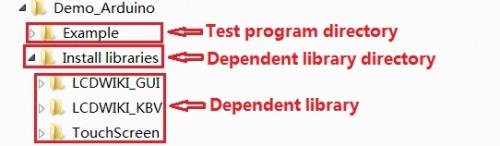
::(1) Decompress the downloaded test package | |||
::(2) Copy the dependent libraries in the <font color="red"> '''Install libraries'''</font> directory in the package (shown below) to the <font color="red">'''libraries'''</font> folder | |||
:::of the Arduino project directory ([http://www.lcdwiki.com/res/PublicFile/Arduino_IDE_Use_Illustration_EN.pdf <font color="red"> '''Don't know the Arduino project directory?'''</font>]) | |||
::[[File:MAR2406-005.jpg|500px]] | |||
*'''Step 4: Compile and download the program to the development board''' | |||
# Open the sample in the Example directory of the package to test, compile and download([http://www.lcdwiki.com/res/PublicFile/Arduino_IDE_Use_Illustration_EN.pdf <font color="red"> '''Don't know how to compile and download?'''</font>]) | |||
*'''Step 5: Observe the running of the program''' | |||
# After the program is downloaded, run it directly and observe the running status. If it can be displayed normally, the program runs | |||
::successfully, as shown in the following figure (take the display_graphics program as an example): | |||
::[[File:MAR2808-040.jpg|150px]] [[File:MAR2808-041.jpg|150px]] | |||
==<font color="blue">Program Download</font> == | |||
* [http://www.lcdwiki.com/res/Program/Arduino/2.8inch/UNO_8BIT_ILI9341_MAR2808_V1.2/2.8inch_Arduino_8BIT_Module_ILI9341_MAR2808_V1.2.zip '''2.8 inch Arduino UNO module package'''] | |||
==<font color="blue">Product Documentation</font> == | |||
* [http://www.lcdwiki.com/res/MAR2808/2.8inch_Arduino_8BIT_Module_MAR2808_User_Manual_EN.pdf '''2.8 inch Arduino UNO Module User Manual'''] | |||
// | * [http://www.lcdwiki.com/images/6/66/MAR2808-001.PNG '''2.8 inch Arduino UNO Module Size Picture'''] | ||
// | * [http://www.lcdwiki.com/res/MAR2808/Altium_2.8_37pin_QD-TFT2802_Package_library.zip '''2.8 inch QD-TFT2802 TFT LCD Schematic and PCB Package Library'''] | ||
* [http://www.lcdwiki.com/res/MAR2808/QD-TFT2802_V1.1.pdf '''2.8 inch TFT Specifications'''] | |||
* [http://www.lcdwiki.com/res/MAR2808/ILI9341_Datasheet.pdf '''Driver IC ILI9341 Data sheet'''] | |||
==<font color="blue"> | ==<font color="blue">Reference Materials</font> == | ||
* [http://www.lcdwiki.com/res/PublicFile/Arduino_IDE_Use_Illustration_EN.pdf '''Arduino IDE software use illustration'''] | |||
* [http://www.lcdwiki.com/res/PublicFile/C51_Keil%26stc-isp_Use_Illustration_EN.pdf '''C51 Keil and stc-isp software use illustration'''] | |||
* [http://www.lcdwiki.com/res/PublicFile/STM32_Keil_Use_Illustration_EN.pdf '''STM32 keil software use illustration'''] | |||
* [http://www.lcdwiki.com/res/PublicFile/PCtoLCD2002_Use_Illustration_EN.pdf '''PCtoLCD2002 software use illustration'''] | |||
* [http://www.lcdwiki.com/res/PublicFile/Image2Lcd_Use_Illustration_EN.pdf '''Image2Lcd software use illustration'''] | |||
* [http://www.lcdwiki.com/Chinese_and_English_display_modulo_settings '''Chinese and English display modulo settings'''] | |||
==<font color="blue">Common | ==<font color="blue">Common Software</font> == | ||
* [http://www.lcdwiki.com/res/software/PCtoLCD2002.zip '''PCtoLCD2002'''] | |||
* [http://www.lcdwiki.com/res/software/Image2Lcd.zip '''Image2Lcd'''] | |||
[[#top|BACK TO TOP]] | [[#top|BACK TO TOP]] | ||
Latest revision as of 14:54, 2 November 2019
Product Video
Product Picture


Product Description
- Supports development boards such as Arduino UNO and Mega2560 for plug-in use without wiring
- 320X240 resolution, clear display, support for touch function
- Support 16-bit RGB 65K color display, display rich colors
- 8-bit parallel bus, faster than serial SPI refresh
- On-board 5V/3.3V level shifting IC, compatible with 5V/3.3V operating voltage
- Easy to expand the experiment with SD card slot
- Provides an Arduino library with a rich sample program
- Military-grade process standards, long-term stable work
- Provide underlying driver technical support
Product Parameters
| Name | Parameter |
| Display Color | RGB 65K color |
| SKU | MAR2808 |
| Screen Size | 2.8(inch) |
| Type | TFT |
| Driver IC | ILI9341 |
| Resolution | 320*240 (Pixel) |
| Module Interface | 8-bit parallel interface |
| Active Area | 43.2*57.6(mm) |
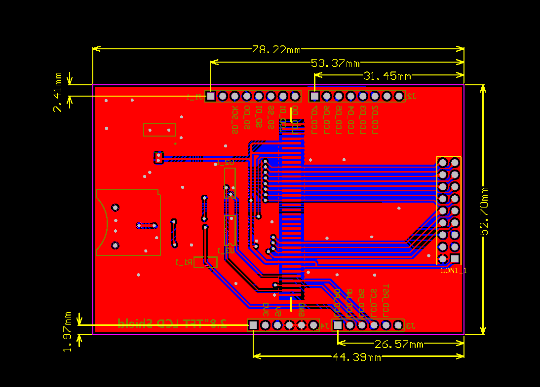
| Module PCB Size | 52.70*78.22(mm) |
| Operating Temperature | -20℃~60℃ |
| Storage Temperature | -30℃~70℃ |
| Operating Voltage | 5V/3.3V |
| Power Consumption | TBD |
| Product Weight(Package containing) | 44(g) |
Interface Definition

| Number | Pin Label | Pin Description |
| 1 | LCD_RST | LCD bus reset signal, low level reset |
| 2 | LCD_CS | LCD bus chip select signal, low level enable |
| 3 | LCD_RS | LCD bus command / data selection signal,
low level: command, high level: data |
| 4 | LCD_WR | LCD bus write signal |
| 5 | LCD_RD | LCD bus read signal |
| 6 | GND | Power ground |
| 7 | 5V | 5V power input |
| 8 | 3V3 | 3.3V power input, this pin can be disconnected |
| 9 | LCD_D0 | LCD 8-bit data Bit0 |
| 10 | LCD_D1 | LCD 8-bit data Bit1 |
| 11 | LCD_D2 | LCD 8-bit data Bit2 |
| 12 | LCD_D3 | LCD 8-bit data Bit3 |
| 13 | LCD_D4 | LCD 8-bit data Bit4 |
| 14 | LCD_D5 | LCD 8-bit data Bit5 |
| 15 | LCD_D6 | LCD 8-bit data Bit6 |
| 16 | LCD_D7 | LCD 8-bit data Bit7 |
| 17 | SD_SS | SD card SPI bus chip select signal, low level enable |
| 18 | SD_DI | SD card SPI bus MOSI signal |
| 19 | SD_DO | SD card SPI bus MISO signal |
| 20 | SD_SCK | SD card SPI bus clock signal |
Connect to Arduino

|

|
|---|---|
| Arduino UNO direct insertion picture | Arduino Mega2560 direct insertion picture |
How to use on Arduino
- Step 1: Download the test program
- Download the Arduino test program from the Program Download column
- For a description of the relevant test procedures, please refer to the test program documentation in the package
- Step 2: Connect the Arduino development board
- Plug the module directly into the Arduino development board ( Do not plug in?)
- After the module is plugged in, power on the Arduino board
- Step 3: Copy the dependent library
- Make sure the Arduino IDE is installed on your computer (if it is not installed: Arduino IDE download URL)
- After installing the Arduino IDE, you need to copy the dependent library to the Arduino project directory as follows:
- (1) Decompress the downloaded test package
- (2) Copy the dependent libraries in the Install libraries directory in the package (shown below) to the libraries folder
- of the Arduino project directory ( Don't know the Arduino project directory?)

- Step 4: Compile and download the program to the development board
- Open the sample in the Example directory of the package to test, compile and download( Don't know how to compile and download?)
- Step 5: Observe the running of the program
- After the program is downloaded, run it directly and observe the running status. If it can be displayed normally, the program runs
- successfully, as shown in the following figure (take the display_graphics program as an example):


Program Download
Product Documentation
- 2.8 inch Arduino UNO Module User Manual
- 2.8 inch Arduino UNO Module Size Picture
- 2.8 inch QD-TFT2802 TFT LCD Schematic and PCB Package Library
- 2.8 inch TFT Specifications
- Driver IC ILI9341 Data sheet
Reference Materials
- Arduino IDE software use illustration
- C51 Keil and stc-isp software use illustration
- STM32 keil software use illustration
- PCtoLCD2002 software use illustration
- Image2Lcd software use illustration
- Chinese and English display modulo settings