More actions
| Line 75: | Line 75: | ||
==<font color="blue">Interface Definition</font> == | ==<font color="blue">Interface Definition</font> == | ||
[[文件:MAR2406-007.png|左|500x500px]] | |||
{| class="wikitable" border="1" style="width: 550px; background-color: white;" | |||
|- | |||
| align="center" |序号 | |||
| align="center" |标号 | |||
| align="center" |引脚说明 | |||
|- | |||
| align="center" |1 | |||
| align="center" |LCD_RST | |||
|LCD总线复位信号,低电平复位 | |||
|- | |||
| align="center" |2 | |||
| align="center" |LCD_CS | |||
|LCD总线片选信号,低电平使能 | |||
|- | |||
| align="center" |3 | |||
| align="center" |LCD_RS | |||
|LCD总线命令/数据选择信号,低电平:命令,高电平:数据 | |||
|- | |||
| align="center" |4 | |||
| align="center" |LCD_WR | |||
|LCD总线写信号 | |||
|- | |||
| align="center" |5 | |||
| align="center" |LCD_RD | |||
|LCD总线读信号 | |||
|- | |||
| align="center" |6 | |||
| align="center" |GND | |||
|电源地 | |||
|- | |||
| align="center" |7 | |||
| align="center" |5V | |||
|5V电源输入 | |||
|- | |||
| align="center" |8 | |||
| align="center" |3V3 | |||
|NC此引脚可不接 | |||
|- | |||
| align="center" |9 | |||
| align="center" |LCD_D0 | |||
|LCD 8位数据Bit0 | |||
|- | |||
| align="center" |10 | |||
| align="center" |LCD_D1 | |||
|LCD 8位数据Bit1 | |||
|- | |||
| align="center" |11 | |||
| align="center" |LCD_D2 | |||
|LCD 8位数据Bit2 | |||
|- | |||
| align="center" |12 | |||
| align="center" |LCD_D3 | |||
|LCD 8位数据Bit3 | |||
|- | |||
| align="center" |13 | |||
| align="center" |LCD_D4 | |||
|LCD 8位数据Bit4 | |||
|- | |||
| align="center" |14 | |||
| align="center" |LCD_D5 | |||
|LCD 8位数据Bit5 | |||
|- | |||
| align="center" |15 | |||
| align="center" |LCD_D6 | |||
|LCD 8位数据Bit6 | |||
|- | |||
| align="center" |16 | |||
| align="center" |LCD_D7 | |||
|LCD 8位数据Bit7 | |||
|- | |||
| align="center" |17 | |||
| align="center" |SD_SS | |||
|SD卡SPI总线片选信号,低电平使能 | |||
|- | |||
| align="center" |18 | |||
| align="center" |SD_DI | |||
|SD卡SPI总线MOSI信号 | |||
|- | |||
| align="center" |19 | |||
| align="center" |SD_DO | |||
|SD卡SPI总线MISO信号 | |||
|- | |||
| align="center" |20 | |||
| align="center" |SD_SCK | |||
|SD卡SPI总线时钟信号 | |||
|} | |||
==<font color="blue">Product Documentation</font> == | ==<font color="blue">Product Documentation</font> == | ||
Revision as of 15:46, 22 November 2018
Product Video
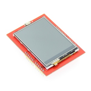
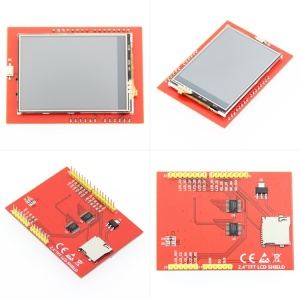
Product Picture
Product Description
- Supports development boards such as Arduino UNO and Mega2560 for plug-in use without wiring
- 320X240 resolution, clear display, support for touch function
- Support 16-bit RGB 65K color display, display rich colors
- 8-bit parallel bus, faster than serial SPI refresh
- On-board 5V/3.3V level shifting IC, compatible with 5V/3.3V operating voltage
- Easy to expand the experiment with SD card slot
- Provides an Arduino library with a rich sample program
- Military-grade process standards, long-term stable work
- Provide underlying driver technical support
Product Parameters
| Name | Parameter |
| Display Color | RGB 65K color |
| SKU | MAR2406 |
| Screen Size | 2.4(inch) |
| Type | TFT |
| Driver IC | ILI9341 |
| Resolution | 320*240 (Pixel) |
| Module Interface | 8-bit parallel interface |
| Active Area | 48.96*36.72(mm) |
| Module PCB Size | 72.20*52.7(mm) |
| Operating Temperature | -20℃~70℃ |
| Storage Temperature | -40℃~70℃ |
| Operating Voltage | 5V/3.3V |
| Power Consumption | About 90mw |
| Product Weight | About 25(g) |
Interface Definition
| 序号 | 标号 | 引脚说明 |
| 1 | LCD_RST | LCD总线复位信号,低电平复位 |
| 2 | LCD_CS | LCD总线片选信号,低电平使能 |
| 3 | LCD_RS | LCD总线命令/数据选择信号,低电平:命令,高电平:数据 |
| 4 | LCD_WR | LCD总线写信号 |
| 5 | LCD_RD | LCD总线读信号 |
| 6 | GND | 电源地 |
| 7 | 5V | 5V电源输入 |
| 8 | 3V3 | NC此引脚可不接 |
| 9 | LCD_D0 | LCD 8位数据Bit0 |
| 10 | LCD_D1 | LCD 8位数据Bit1 |
| 11 | LCD_D2 | LCD 8位数据Bit2 |
| 12 | LCD_D3 | LCD 8位数据Bit3 |
| 13 | LCD_D4 | LCD 8位数据Bit4 |
| 14 | LCD_D5 | LCD 8位数据Bit5 |
| 15 | LCD_D6 | LCD 8位数据Bit6 |
| 16 | LCD_D7 | LCD 8位数据Bit7 |
| 17 | SD_SS | SD卡SPI总线片选信号,低电平使能 |
| 18 | SD_DI | SD卡SPI总线MOSI信号 |
| 19 | SD_DO | SD卡SPI总线MISO信号 |
| 20 | SD_SCK | SD卡SPI总线时钟信号 |


