More actions
| Line 66: | Line 66: | ||
==<font color="blue">Interface definition</font> == | ==<font color="blue">Interface definition</font> == | ||
[[file:MAR2808-008.jpg|800x800px]] | |||
{| class="wikitable" border="1" style="width: 500px; background-color: white;" | |||
|- | |||
| align="center" |number | |||
| align="center" |label | |||
| align="center" |pin description | |||
|- | |||
| align="center" |1 | |||
| align="center" |LCD_RST | |||
|LCD bus reset signal | |||
|- | |||
| align="center" |2 | |||
| align="center" |LCD_CS | |||
|LCD bus chip select signal | |||
|- | |||
| align="center" |3 | |||
| align="center" |LCD_RS | |||
|LCD bus command/data select signal | |||
|- | |||
| align="center" |4 | |||
| align="center" |LCD_WR | |||
|LCD bus write signal | |||
|- | |||
| align="center" |5 | |||
| align="center" |LCD_RD | |||
|LCD bus read signal | |||
|- | |||
| align="center" |6 | |||
| align="center" |GND | |||
|power ground | |||
|- | |||
| align="center" |7 | |||
| align="center" |5V | |||
|5V power input | |||
|- | |||
| align="center" |8 | |||
| align="center" |3V3 | |||
|NC this pin can not be connected | |||
|- | |||
| align="center" |9 | |||
| align="center" |LCD_D0 | |||
|LCD 8-bit data Bit0 | |||
|- | |||
| align="center" |10 | |||
| align="center" |LCD_D1 | |||
|LCD 8-bit data Bit1 | |||
|- | |||
| align="center" |11 | |||
| align="center" |LCD_D2 | |||
|LCD 8-bit data Bit2 | |||
|- | |||
| align="center" |12 | |||
| align="center" |LCD_D3 | |||
|LCD 8-bit data Bit3 | |||
|- | |||
| align="center" |13 | |||
| align="center" |LCD_D4 | |||
|LCD 8-bit data Bit4 | |||
|- | |||
| align="center" |14 | |||
| align="center" |LCD_D5 | |||
|LCD 8-bit data Bit5 | |||
|- | |||
| align="center" |15 | |||
| align="center" |LCD_D6 | |||
|LCD 8-bit data Bit6 | |||
|- | |||
| align="center" |16 | |||
| align="center" |LCD_D7 | |||
|LCD 8-bit data Bit7 | |||
|- | |||
| align="center" |17 | |||
| align="center" |SD_SS | |||
|SD card SPI bus chip select signal | |||
|- | |||
| align="center" |18 | |||
| align="center" |SD_DI | |||
|SD card SPI bus MOSI signal | |||
|- | |||
| align="center" |19 | |||
| align="center" |SD_DO | |||
|SD card SPI bus MISO signal | |||
|- | |||
| align="center" |20 | |||
| align="center" |SD_SCK | |||
|SD card SPI bus clock signal | |||
|} | |||
==<font color="blue">Product size</font> == | ==<font color="blue">Product size</font> == | ||
Revision as of 09:47, 30 June 2018
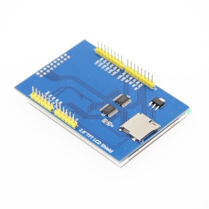
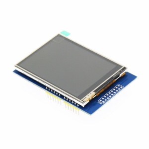
Product picture
Product description
- Support development boards such as ArduinoUNO and Mega2560 for use without wiring
- 320X240 HD resolution and support touch function
- Supports 16-bit RGB 65K color display and rich color display
- using 8-bit parallel bus, refresh faster than serial SPI
- With SD card slot to facilitate the expansion of the experiment
- Provide Arduino library, provide a wealth of sample programs
- Military-grade process standards, long-term work stably
- Provides underlying driver technology support
- Data Acquisition: See Driver download
Product parameters
| name | parameter |
| SKU | MAR2808 |
| size | 2.8(inch) |
| type | TFT |
| driver chip | ILI9341 |
| resolution | 320*240 (Pixel) |
| module interface | 8-bit parallel interface |
| effective display area | 57.6x43.2(mm) |
| module PCB size | 78.22x52.7(mm) |
| operating temperature | -20℃~70℃ |
| operating Voltage | 5V |
| power consumption | about 90mw |
| product weight | 25(g) |
Interface definition
| number | label | pin description |
| 1 | LCD_RST | LCD bus reset signal |
| 2 | LCD_CS | LCD bus chip select signal |
| 3 | LCD_RS | LCD bus command/data select signal |
| 4 | LCD_WR | LCD bus write signal |
| 5 | LCD_RD | LCD bus read signal |
| 6 | GND | power ground |
| 7 | 5V | 5V power input |
| 8 | 3V3 | NC this pin can not be connected |
| 9 | LCD_D0 | LCD 8-bit data Bit0 |
| 10 | LCD_D1 | LCD 8-bit data Bit1 |
| 11 | LCD_D2 | LCD 8-bit data Bit2 |
| 12 | LCD_D3 | LCD 8-bit data Bit3 |
| 13 | LCD_D4 | LCD 8-bit data Bit4 |
| 14 | LCD_D5 | LCD 8-bit data Bit5 |
| 15 | LCD_D6 | LCD 8-bit data Bit6 |
| 16 | LCD_D7 | LCD 8-bit data Bit7 |
| 17 | SD_SS | SD card SPI bus chip select signal |
| 18 | SD_DI | SD card SPI bus MOSI signal |
| 19 | SD_DO | SD card SPI bus MISO signal |
| 20 | SD_SCK | SD card SPI bus clock signal |


