More actions
Product video
VideoService "youku" not recognized.
Product picture
Product description
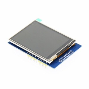
- Support development boards such as ArduinoUNO and Mega2560 for use without wiring
- 320X240 HD resolution and support touch function
- Supports 16-bit RGB 65K color display and rich color display
- using 8-bit parallel bus, refresh faster than serial SPI
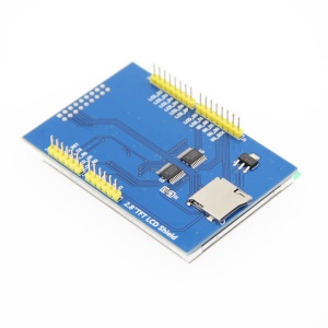
- With SD card slot to facilitate the expansion of the experiment
- Provide Arduino library, provide a wealth of sample programs
- Military-grade process standards, long-term work stably
- Provides underlying driver technology support
- Data Acquisition: See Driver download
Product parameters
| name | parameter |
| SKU | MAR2808 |
| size | 2.8(inch) |
| type | TFT |
| driver chip | ILI9341 |
| resolution | 320*240 (Pixel) |
| module interface | 8-bit parallel interface |
| effective display area | 57.6x43.2(mm) |
| module PCB size | 78.22x52.7(mm) |
| operating temperature | -20℃~70℃ |
| operating Voltage | 5V |
| power consumption | about 90mw |
| product weight | 25(g) |
Interface definition

| number | label | pin description |
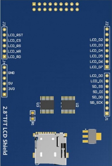
| 1 | LCD_RST | LCD bus reset signal |
| 2 | LCD_CS | LCD bus chip select signal |
| 3 | LCD_RS | LCD bus command/data select signal |
| 4 | LCD_WR | LCD bus write signal |
| 5 | LCD_RD | LCD bus read signal |
| 6 | GND | power ground |
| 7 | 5V | 5V power input |
| 8 | 3V3 | NC this pin can not be connected |
| 9 | LCD_D0 | LCD 8-bit data Bit0 |
| 10 | LCD_D1 | LCD 8-bit data Bit1 |
| 11 | LCD_D2 | LCD 8-bit data Bit2 |
| 12 | LCD_D3 | LCD 8-bit data Bit3 |
| 13 | LCD_D4 | LCD 8-bit data Bit4 |
| 14 | LCD_D5 | LCD 8-bit data Bit5 |
| 15 | LCD_D6 | LCD 8-bit data Bit6 |
| 16 | LCD_D7 | LCD 8-bit data Bit7 |
| 17 | SD_SS | SD card SPI bus chip select signal |
| 18 | SD_DI | SD card SPI bus MOSI signal |
| 19 | SD_DO | SD card SPI bus MISO signal |
| 20 | SD_SCK | SD card SPI bus clock signal |
Product size
Product size drawing:
Hardware description
Hardware schematic:Arduino 2.8 inch display module schematic.pdf
Using Instructions
Arduino platform using instructions
1.Wiring instructions
| connect with UNO development board | Connect with Mega2560 Development Board | ||
|---|---|---|---|
| pins on the module | UNO microcontroller pin | pins on the module | Mega2560 microcontroller pin |
| LCD_RST | A4 | LCD_RST | 5V |
| LCD_CS | A3 | LCD_CS | GND |
| LCD_RS | A2 | LCD_RS | 21 |
| LCD_WR | A1 | LCD_WR | 20 |
| LCD_RD | A0 | LCD_RD | A0 |
| GND | GND | GND | GND |
| 5V | 5V | 5V | 5V |
| LCD_D0 | 8 | LCD_D0 | 8 |
| LCD_D1 | 9 | LCD_D1 | 9 |
| LCD_D2 | 2 | LCD_D2 | 2 |
| LCD_D3 | 3 | LCD_D3 | 3 |
| LCD_D4 | 4 | LCD_D4 | 4 |
| LCD_D5 | 5 | LCD_D5 | 5 |
| LCD_D6 | 6 | LCD_D6 | 6 |
| LCD_D7 | 7 | LCD_D7 | 7 |
| SD_SS | 10 | SD_SS | 10 |
| SD_DI | 11 | SD_DI | 11 |
| SD_DO | 12 | SD_DO | 12 |
| SD_SCK | 13 | SD_SCK | 13 |
2.operating instructions
Install the Arduino IDE software on your computer before doing the following
a.Connect the 2.8-inch display module to the Arduino development board according to the wiring instructions and power it on (note the development board model)
b.Download the 2.8 inch display module package from Driver download column
c.Extract the data package,open the install library folder,you can see the LCDWIKI_GUI,LCDWIKI_KBV and touch screen these three libraries,as shown below:
d.Copy the three libraries:LCDWIKI_GUI,LCDWIKI_KBV,and touch screen to the directory where the Arduino project files are located,
The default directory for Arduino project files is "C:\Users\Administrator\Documents\Arduino",You can define it yourself as follows:
Open Arduino IDE software,click File->Preferences to define the directory where Arduino project files are located,as shown in the following figure:
e.Open the Example folder in the package, you can see there are 11 test examples, as shown below:
f.Open any test example,eg open "Example_02_clear_screen"
g.After opening the "Example_02_clear_screen" test program,click the Tools button to select the board model and port number,as shown in the following figure:
If the development board model selection Mega, you also need to select the processor model, for the 2.8-inch display module,
we only select the ATmega2560 processor, as shown below:
h.Click the upload button to compile and download. When "Done Uploading" is displayed,the program has been successfully downloaded to the development board,
as shown in the following figure:
i.If the 2.8-inch display module is continuously displayed in black, white, red, green, and blue, the program runs successfully.
Matters needing attention
a.The display module uses 8-bit parallel port to transfer data,so the LCDWIKI library also needs to be set to 8-bit mode (since the LCDWIKI library supports
both 8-bit and 16-bit modes),the modification method is as follows:
Open the file LCDWKI_KBV\lcd_mode.h and set the CONFIG_USE_8BIT_BUS macro to 1, as shown below:
//if using 8bit mode,set the below macro definition to 1
//if using 16bit mode,set the below macro definition to 0
#define CONFIG_USE_8BIT_BUS 1
STM32 platform using instructions
1.Wiring instructions
| pins on the module | STM32 corresponding wiring pin |
|---|---|
| LCD_RST | PC5 |
| LCD_CS | PC9 |
| LCD_RS | PC8 |
| LCD_WR | PC7 |
| LCD_RD | PC6 |
| GND | GND |
| 5V | 5V |
| LCD_D0 | PB8 |
| LCD_D1 | PB9 |
| LCD_D2 | PB10 |
| LCD_D3 | PB11 |
| LCD_D4 | PB12 |
| LCD_D5 | PB13 |
| LCD_D6 | PB14 |
| LCD_D7 | PB15 |
| SD_SS | NC(No need to connect) |
| SD_DI | NC(No need to connect) |
| SD_DO | NC(No need to connect) |
| SD_SCK | NC(No need to connect) |
2.operating instructions
Before you do the following, first install the keil software on your computer
a.Connect the 2.8-inch display module to the STM32 development board and power it up according to the wiring instructions
b.Download the 2.8 inch display module package from Driver download column
c.Unpack the package, open the "3-STM32测试程序\STM32_Demo_STM32F103RCT6_8BIT\STM32综合测试程序ILI9341_IO模拟\USER" folder,
find the "TOUCH.uvproj" file, double-click to open, as shown below:
d.After opening the project, first make JTAG settings, the setup steps are as follows (if the project has been set, you do not need to set it):
Connect JTAG to the computer and development board, click the magic wand icon -> Debug-> drop-down menu to select J-LINK/J-TRACE Cortex, as shown below:
Next click Settings, set ort to SW, Max to 2MHz, as shown below:
e.Set flash, the setup steps are as follows (if the project has been set, you do not need to set it):
First select the MCU model, click the magic wand icon -> Device -> select STM32F103RC MCU model, as shown below:
Then select the flash model, click Utilities->Settings->Add->Select STM32F10x High-density Flash->Add, as shown below:
f.Compile the project, click the compile button to compile the project. If the "FromELF: creating hex file..." prompt appears, the compilation is successful,
as shown in the following figure:
g.Download the program, click the download button, download the hex file to the development board, if the “Programming Done. Verify OK.” prompt appears,
the download is successful, as shown below:
h.If the module displays characters and graphics normally, the program runs successfully.
Matters needing attention
a.When downloading the program, if the following error occurs, the JTAG setting is incorrect. Please follow the instructions in step d to set it:
b.If the following error occurs, the flash setting is incorrect. Please follow the instructions in step e:
c.If the module does not display any after the program is successfully downloaded, you need to press the reset button to reset
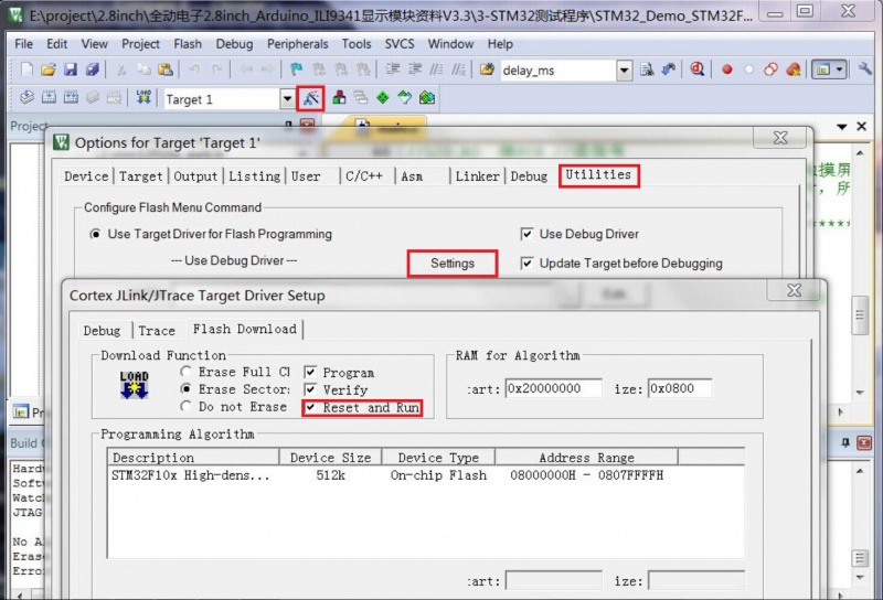
Follow the steps below to run the program directly after downloading successfully (do not need to press the reset button)
Click the magic wand icon -> Utilities->Settings-> check Reset and run, as shown below:
Driver download
baiduyun download:2.8inch_Arduino_8bit_ILI9341_V1.0.zip
Local download:2.8inch_Arduino_8bit_ILI9341_V1.0.zip
Common software description
Character modulo software PCtoLCD2002 download:PCtoLCD2002.zip
Image modulo software Image2Lcd Download:Image2Lcd.zip


