More actions
Product Video
Product Picture
Product Description
- 4.0-inch color screen, support 16BIT RGB 65K color display, display rich colors
- 320x480 resolution for clear display
- Supports 8-bit and 16-bit parallel bus transmission with fast transfer speed
- Supports ALIENTEK STM32 Mini, Elite, WarShip, Explorer, and Apollo development boards TFTLCD for direct plug-in use
- Support for touch function
- Support SD card function expansion
- Provides a rich sample program for STM32 and C51 platforms
- Military-grade process standards, long-term stable work
- Provide underlying driver technical support
Product Parameters
| Name | Parameter |
| Display Color | 16BIT RGB 65K color |
| SKU | MRB3951 |
| Screen Size | 4.0(inch) |
| Type | TFT |
| Driver IC | ST7796S |
| Resolution | 480*320 (Pixel) |
| Module Interface | 8bit or 16Bit parallel interface |
| Active Area | 83.52x55.68(mm) |
| Module PCB Size | 61.98x108.80 (mm) |
| Operating Temperature | -10℃~60℃ |
| Storage Temperature | -20℃~70℃ |
| Operating Voltage | 3.3V~5V |
| Power Consumption | TBD |
| Product Weight | TBD |
Interface Definition
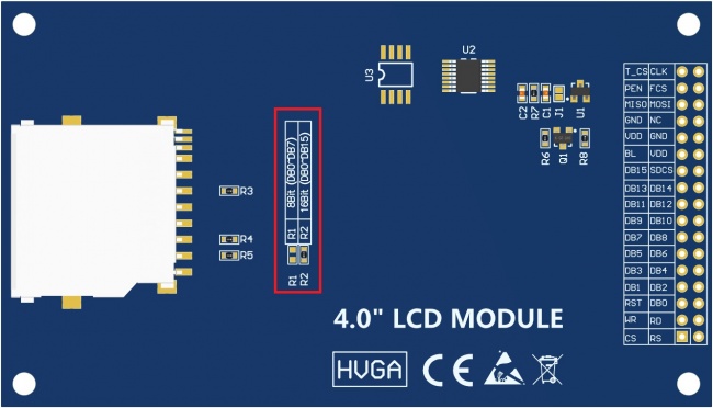
8-bit and 16-bit data bus mode switching circuits in the blue box (this module uses 16-bit mode)
| Number | Pin Label | Description |
| 1 | CS | LCD reset control pin( low level enable) |
| 2 | RS | LCD register / data selection control pin(high level: register, low level: data) |
| 3 | WR | LCD write control pin |
| 4 | RD | LCD read control pin |
| 5 | RST | LCD reset control pin( low level reset) |
| 6 | DB0 | LCD data bus low 8-bit pin |
| 7 | DB1 | |
| 8 | DB2 | |
| 9 | DB3 | |
| 10 | DB4 | |
| 11 | DB5 | |
| 12 | DB6 | |
| 13 | DB7 | |
| 14 | DB8 | LCD data bus high 8-bit pin (not used in 8-bit data bus mode) |
| 15 | DB9 | |
| 16 | DB10 | |
| 17 | DB11 | |
| 18 | DB12 | |
| 19 | DB13 | |
| 20 | DB14 | |
| 21 | DB15 | |
| 22 | SDCS | SD card selection control pin (used when using the SD card expansion function, this test program is not used) |
| 23 | BL | LCD backlight control pin(High level light) |
| 24 | VDD | Module power positive pin (module has integrated voltage regulator IC, so the power supply can be connected to 5V or 3.3V) |
| 25 | VDD | |
| 26 | GND | Module power ground pin |
| 27 | GND | |
| 28 | NC | LCD backlight power positive pin (default shared onboard backlight power supply, this pin can not be connected) |
| 29 | MISO | Touch screen SPI bus data input pin |
| 30 | MOSI | Touch screen SPI bus data output pin |
| 31 | PEN | Touch screen interrupt detection pin(Low level when a touch occurs) |
| 32 | FCS | Flash chip select control pin (used when using the Flash extension function, this test program is not used) |
| 33 | T_CS | Touch screen IC chip select control pin(Low level enable) |
| 34 | CLK | Touch screen SPI bus clock control pin |
Product Documentation
- 4.0inch 16bit Parallel-Port Module User Manual
- 4.0inch TFTLCD Specification
- 4.0inch 16bit Parallel-Port Module Size Picture(pdf Version)
- 4.0inch 16bit Parallel-Port Module Size Picture(jpg Version)
- 4.0inch 16bit Parallel-Port Module Schematic
- 4.0inch 16bit Parallel-Port Module LCD Schematic and PCB Package Library
- Driver IC ST7796S Data sheet
Program Download
Reference Materials
- C51 Keil and stc-isp software use illustration
- STM32 keil software use illustration
- PCtoLCD2002 software use illustration
- Image2Lcd software use illustration
- Chinese and English display modulo settings
How to use on STM32 development board
This module is compatible with the ALIENTEK STM32 development board. The specific usage is as follows:
- Step 1: Download the test program
- Download the STM32 test program from the Program Download column
- For a description of the relevant test procedures, please refer to the test program documentation in the package
- Step 2: Connect the STM32 development board
- Find the TFTLCD Slot on the development board, connect the module pins and Slot(For example, the module CS pin corresponds to the slot CS pin), and then plug them directly into the Slot
- Step 3: Compile and download the program to the development board
- Compile and download the program you need to test to the STM32 development board( Don't know how to compile and download?)
- Step 4: Observe the running of the program
- After the program is finished, observe the running status of the program. If it can be displayed normally, the program runs successfully.

