
更多语言
更多操作
无编辑摘要 |
无编辑摘要 |
||
| 第3行: | 第3行: | ||
{{#widget:StyledHeader|color=#bc1d46}} | {{#widget:StyledHeader|color=#bc1d46}} | ||
[[en:5inch ESP32-S3 Display ES3R50T]] | [[en:5inch ESP32-S3 Display ES3R50T]] | ||
= | = Product Images = | ||
{{gallery|File:ES3R50P-1.png|ES3R50T-TopView|File:ES3C50P-1.png|ES3R50T-BottomView|width=256px|height=256px}} | {{gallery|File:ES3R50P-1.png|ES3R50T-TopView|File:ES3C50P-1.png|ES3R50T-BottomView|width=256px|height=256px}} | ||
= | = Product Introduction = | ||
* | * Equipped with ESP32-S3 chip, powerful performance and abundant development resources for convenient development | ||
* 5 | * 5-inch color screen with 800×480 resolution, rich display colors (RGB565) | ||
* | * Abundant peripheral interfaces for easy connection of SPI, UART and other external devices | ||
* | * Built-in resistive touch screen for convenient human-machine interaction | ||
* | * Standard Type-C interface for program uploading and power supply | ||
* | * Onboard Micro TF card slot for storage expansion | ||
* | * Built-in audio interface for speaker connection and audio playback | ||
* | * Complete demo programs provided for easy learning | ||
* | * Technical support for underlying drivers with online updated WIKI documents | ||
= | = Product Parameters = | ||
== ESP32 | == ESP32 Main Controller Parameters == | ||
{| class="wikitable prettytable" | {| class="wikitable prettytable" | ||
! align="center" |'''<big> | ! align="center" |'''<big>Item</big>''' | ||
! align="center" |'''<big> | ! align="center" |'''<big>Parameter</big>''' | ||
|- | |- | ||
| align="center" |''' | | align="center" |'''Module Chip''' | ||
| align="center" |ESP32-S3 | | align="center" |ESP32-S3 | ||
|- | |- | ||
| align="center" |'''CPU''' | | align="center" |'''CPU''' | ||
| align="center" |Xtensa LX7 32 | | align="center" |Xtensa LX7 32-bit Dual-Core Processor | ||
|- | |- | ||
| align="center" |''' | | align="center" |'''Max Clock Frequency''' | ||
| align="center" |240MHz | | align="center" |240MHz | ||
|- | |- | ||
| align="center" |''' | | align="center" |'''Storage Resources''' | ||
| align="center" |384 KB ROM + 512KB SRAM | | align="center" |384 KB ROM + 512KB SRAM | ||
+16 KB RTC SRAM + 8M | +16 KB RTC SRAM + 8M Built-in OPI PSRAM + 16M External QSPI Flash | ||
(N16R8) | |||
|- | |- | ||
| align="center" |''' | | align="center" |'''Wi-Fi''' | ||
| align="center" |2.4GHz | | align="center" |2.4GHz, 802.11b/g/n standard | ||
|- | |- | ||
| align="center" |''' | | align="center" |'''Bluetooth''' | ||
| align="center" | | | align="center" |Bluetooth V5.0 BR/EDR & BLE | ||
|- | |- | ||
| align="center" |''' | | align="center" |'''Core Operating Voltage''' | ||
| align="center" |3.0~3.6(V) | | align="center" |3.0~3.6(V) | ||
|} | |} | ||
== | == LCD Screen Parameters == | ||
{| class="wikitable prettytable" | {| class="wikitable prettytable" | ||
! align="center" |'''<big> | ! align="center" |'''<big>Item</big>''' | ||
! align="center" |'''<big> | ! align="center" |'''<big>Parameter</big>''' | ||
|- | |- | ||
| align="center" |''' | | align="center" |'''Screen Size''' | ||
| align="center" |5inch | | align="center" |5inch | ||
|- | |- | ||
| align="center" |''' | | align="center" |'''Panel Type''' | ||
| align="center" |TN | | align="center" |TN | ||
|- | |- | ||
| align="center" |''' | | align="center" |'''Resolution''' | ||
| align="center" |800xRGBx480(pixels) | | align="center" |800xRGBx480(pixels) | ||
|- | |- | ||
| align="center" |''' | | align="center" |'''Active Display Area''' | ||
| align="center" |108.00(W) | | align="center" |108.00(W)×64.80(H) mm | ||
|- | |- | ||
| align="center" |''' | | align="center" |'''Color Depth''' | ||
| align="center" |65K(RGB565) | | align="center" |65K (RGB565) | ||
|- | |- | ||
| align="center" |''' | | align="center" |'''Display Interface''' | ||
| align="center" |RGB565-16Bit | | align="center" |RGB565-16Bit | ||
|- | |- | ||
| align="center" |''' | | align="center" |'''Pixel Pitch''' | ||
| align="center" |0.153(H) | | align="center" |0.153(H)×0.153(V) mm | ||
|- | |- | ||
| align="center" |''' | | align="center" |'''Viewing Angle''' | ||
| align="center" |6 | | align="center" |6 o'clock | ||
|- | |- | ||
| align="center" |''' | | align="center" |'''Typical Backlight Brightness''' | ||
| align="center" |450cd/m<sup>2</sup> | | align="center" |450cd/m<sup>2</sup> | ||
|- | |- | ||
| align="center" |''' | | align="center" |'''Backlight Type''' | ||
| align="center" |White LED | | align="center" |White LED | ||
|- | |- | ||
| align="center" |''' | | align="center" |'''Operating Temperature''' | ||
| align="center" | -20~60 | | align="center" | -20~60℃ | ||
|- | |- | ||
| align="center" |''' | | align="center" |'''Storage Temperature''' | ||
| align="center" | -30~70 | | align="center" | -30~70℃ | ||
|} | |} | ||
== | == Other General Parameters == | ||
{| class="wikitable prettytable" | {| class="wikitable prettytable" | ||
! align="center" |'''<big> | ! align="center" |'''<big>Item</big>''' | ||
! colspan="2" align="center" |'''<big> | ! colspan="2" align="center" |'''<big>Parameter</big>''' | ||
|- | |- | ||
|'''SKU''' | |'''SKU''' | ||
|ES3R50T | |ES3R50T | ||
|- | |- | ||
| align="center" |''' | | align="center" |'''Active Area Size''' | ||
| colspan="2" align="center" |5 inch | | colspan="2" align="center" |5 inch | ||
|- | |- | ||
|''' | |'''Supply Voltage''' | ||
| colspan="2" |5.0V | | colspan="2" |5.0V | ||
|- | |- | ||
|''' | |'''Power Interface''' | ||
| colspan="2" |USB | | colspan="2" |USB Type-C | ||
|- | |- | ||
|''' | |'''Typical Total Current''' | ||
|250mA | |250mA | ||
|- | |- | ||
|''' | |'''Actual Backlight Brightness''' | ||
|450cd/m<sup>2</sup> | |450cd/m<sup>2</sup> | ||
|- | |- | ||
|''' | |'''Typical Power Consumption''' | ||
|1.25W | |1.25W | ||
|- | |- | ||
|''' | |'''Touch Panel Type''' | ||
| | |Resistive Touch Screen | ||
|- | |- | ||
| align="center" |''' | | align="center" |'''Touch Resolution''' | ||
| align="center" |800x480(pixels) | | align="center" |800x480(pixels) | ||
|- | |- | ||
| align="center" |''' | | align="center" |'''Touch Driver IC''' | ||
| align="center" |XPT2046 | | align="center" |XPT2046 | ||
|- | |- | ||
| align="center" |''' | | align="center" |'''Touch Communication Bus''' | ||
| align="center" |SPI | | align="center" |SPI | ||
|- | |- | ||
| align="center" |''' | | align="center" |'''LCD Outline Dimension''' | ||
| colspan="2" align="center" |120.7(W) | | colspan="2" align="center" |120.7(W)×75.9(H)×4.2(D) mm (Excluding FPC cable & adhesive tape) | ||
|- | |- | ||
| align="center" |''' | | align="center" |'''Touch Panel Outline Dimension''' | ||
| align="center" |117.5(W) | | align="center" |117.5(W)×70.2(H) mm (Excluding FPC cable & adhesive tape) | ||
|- | |- | ||
|''' | |'''Module Overall Dimension''' | ||
|137(W) | |137(W)×84(H)×13.75(D) mm | ||
|- | |- | ||
|''' | |'''Operating Temperature''' | ||
| -20~60 | | -20~60℃ | ||
|- | |- | ||
|''' | |'''Storage Temperature''' | ||
| -30~70 | | -30~70℃ | ||
|- | |- | ||
|''' | |'''Weight (Including Package)''' | ||
| | |Resistive Version (ES3R50P): 197 g | ||
|} | |} | ||
= | = Interface Definition = | ||
[[File:ES3C50P-2.png|956x956px]] | [[File:ES3C50P-2.png|956x956px]] | ||
== | == Interface Function Description == | ||
{| class="wikitable prettytable" | {| class="wikitable prettytable" | ||
! align="center" |'''<big> | ! align="center" |'''<big>Interface No.</big>''' | ||
! align="center" |'''<big> | ! align="center" |'''<big>Function Description</big>''' | ||
|- | |- | ||
| align="center" |'''① ESP32-S3''' | | align="center" |'''① ESP32-S3 Chip''' | ||
| | |Main controller of the display module, responsible for controlling onboard and external peripherals. | ||
|- | |- | ||
| align="center" |'''② MicroSD | | align="center" |'''② MicroSD Card Slot''' | ||
| | |For Micro SD card insertion to expand storage space, to store large-capacity files such as font libraries, pictures and audio files. | ||
|- | |- | ||
| align="center" |'''③ | | align="center" |'''③ UART Port''' | ||
|1.25mm | |1.25mm 4P connector, used for serial debugging, firmware uploading and data communication. | ||
|- | |- | ||
| align="center" |'''④ BOOT | | align="center" |'''④ BOOT Button''' | ||
| | |Used to enter download mode or as a normal test button. | ||
Hold this button while powering on the module then release to enter download mode; | |||
Or keep holding BOOT after power-on, press and release the RESET button, then release BOOT to enter download mode. | |||
It can work as a regular button when download mode is not required. | |||
|- | |- | ||
| align="center" |'''⑤ | | align="center" |'''⑤ Type-C Port''' | ||
| | |Main port for power supply and firmware uploading. Connected with auto-download circuit, which can automatically switch to download mode without pressing the BOOT button. | ||
|- | |- | ||
| align="center" |'''⑥ RESET | | align="center" |'''⑥ RESET Button''' | ||
| | |Reset pin for ESP32-S3 main chip and LCD screen, active low when pressed. | ||
|- | |- | ||
| align="center" |'''⑦ | | align="center" |'''⑦ Extended Input Header''' | ||
|1.25mm 4P | |1.25mm 4P connector, leads out GPIO17 & GPIO18 pins. | ||
|- | |- | ||
| align="center" |'''⑧ UART1 | | align="center" |'''⑧ UART1 & USB Header''' | ||
|1.25mm 4P | |1.25mm 4P connector, leads out GPIO17, GPIO18, GPIO19, GPIO20 spare pins. GPIO17/GPIO18 for UART1; GPIO19/GPIO20 for USB differential signals. | ||
|- | |- | ||
| align="center" |'''⑨ SPI | | align="center" |'''⑨ SPI Peripheral Header''' | ||
|1.25mm 4P | |1.25mm 4P connector for external SPI devices, shared with SD card bus. Can be used as general GPIO when SPI peripheral is idle. | ||
|- | |- | ||
| align="center" |'''⑩ | | align="center" |'''⑩ Speaker Header''' | ||
|1.25mm 2P | |1.25mm 2P connector for speaker connection and audio playback. | ||
|} | |} | ||
== ESP32 | == ESP32 Pin Assignment Table == | ||
{| class="wikitable prettytable" | {| class="wikitable prettytable" | ||
! align="center" |''' | ! align="center" |'''On-board Device''' | ||
! align="center" |'''ESP32 | ! align="center" |'''ESP32 GPIO Pin''' | ||
! align="center" |''' | ! align="center" |'''Pin Function Description''' | ||
|- | |- | ||
| rowspan="8" align="center" |''' | | rowspan="8" align="center" |'''LCD Screen''' | ||
| align="center" |IO40 | | align="center" |IO40 | ||
| | |LCD chip select signal, active low | ||
|- | |- | ||
| align="center" |IO46 | | align="center" |IO46 | ||
| | |Data Enable (DE) Control Pin | ||
|- | |- | ||
| align="center" |IO41 | | align="center" |IO41 | ||
| | |Vertical Sync (VSYNC) Control Pin | ||
|- | |- | ||
| align="center" |IO39 | | align="center" |IO39 | ||
| | |Horizontal Sync (HSYNC) Control Pin | ||
|- | |- | ||
| align="center" |IO42 | | align="center" |IO42 | ||
| | |Pixel Clock (PCLK) Control Pin | ||
|- | |- | ||
| align="center" | | | align="center" |IO45/48/47/21/14 | ||
|5 | |5-bit Red Data Pins | ||
|- | |- | ||
| align="center" |IO5/6/7/15/16/4 | | align="center" |IO5/6/7/15/16/4 | ||
|6 | |6-bit Green Data Pins | ||
|- | |- | ||
| align="center" |IO8/3/46/9/1 | | align="center" |IO8/3/46/9/1 | ||
|5 | |5-bit Blue Data Pins | ||
|- | |- | ||
| rowspan="4" align="center" |''' | | rowspan="4" align="center" |'''Resistive Touch Screen''' | ||
| align="center" |IO12 | | align="center" |IO12 | ||
| | |SPI Clock (SCLK) for XPT2046 touch IC | ||
|- | |- | ||
| align="center" |IO13 | | align="center" |IO13 | ||
| | |SPI MISO (Master Input, data read) | ||
|- | |- | ||
| align="center" |IO11 | | align="center" |IO11 | ||
| | |SPI MOSI (Master Output, data write) | ||
|- | |- | ||
| align="center" |IO38 | | align="center" |IO38 | ||
| | |Touch SPI Chip Select (CS) Pin | ||
|- | |- | ||
| rowspan="4" align="center" |'''MicroSD | | rowspan="4" align="center" |'''MicroSD Card''' | ||
| align="center" |IO10 | | align="center" |IO10 | ||
|SD | |SD Card SPI Chip Select (CS) Pin | ||
|- | |- | ||
| align="center" |IO11 | | align="center" |IO11 | ||
|SD | |SD SPI MOSI (Master Output, data write) | ||
|- | |- | ||
| align="center" |IO13 | | align="center" |IO13 | ||
|SD | |SD SPI MISO (Master Input, data read) | ||
|- | |- | ||
| align="center" |IO12 | | align="center" |IO12 | ||
|SD | |SD SPI Clock (SCLK) Pin | ||
|- | |- | ||
| rowspan="2" align="center" |''' | | rowspan="2" align="center" |'''Buttons''' | ||
| align="center" |IO0 | | align="center" |IO0 | ||
| | |BOOT strapping button: hold during power-on to enter download mode | ||
|- | |- | ||
| align="center" |EN | | align="center" |EN | ||
|ESP32-S3 | |Global active-low reset pin (shared for ESP32-S3 and LCD) | ||
|- | |- | ||
| rowspan="2" align="center" |''' | | rowspan="2" align="center" |'''UART0''' | ||
| align="center" |RXD0(IO43) | | align="center" |RXD0(IO43) | ||
| | |UART0 receive pin, usable as general GPIO if serial is unused | ||
|- | |- | ||
| align="center" |TXD0(IO44) | | align="center" |TXD0(IO44) | ||
| | |UART0 transmit pin, usable as general GPIO if serial is unused | ||
|- | |- | ||
| rowspan="4" align="center" |'''SPI | | rowspan="4" align="center" |'''External SPI Header''' | ||
| align="center" |IO19 | | align="center" |IO19 | ||
|SPI | |External SPI chip select pin, general GPIO available if USB function is disabled | ||
|- | |- | ||
| align="center" |IO11 | | align="center" |IO11 | ||
|SPI | |SPI MOSI pin, general GPIO available if SD card is unused | ||
|- | |- | ||
| align="center" |IO13 | | align="center" |IO13 | ||
|SPI | |SPI MISO pin, general GPIO available if SD card is unused | ||
|- | |- | ||
| align="center" |IO12 | | align="center" |IO12 | ||
|SPI | |SPI SCLK pin, general GPIO available if SD card is unused | ||
|- | |- | ||
| rowspan="2" align="center" |''' | | rowspan="2" align="center" |'''Extended GPIO Pins''' | ||
| align="center" |IO18 | | align="center" |IO18 | ||
| | |General GPIO when touch & audio & SD card are disabled | ||
|- | |- | ||
| align="center" |IO17 | | align="center" |IO17 | ||
| | |General GPIO when audio & SD card are disabled | ||
|- | |- | ||
| rowspan="2" align="center" |'''USB''' | | rowspan="2" align="center" |'''USB Interface''' | ||
| align="center" |IO19 | | align="center" |IO19 | ||
|USB | |USB D- differential data line | ||
|- | |- | ||
| align="center" |IO20 | | align="center" |IO20 | ||
|USB | |USB D+ differential data line | ||
|- | |- | ||
| rowspan="2" align="center" |'''UART1''' | | rowspan="2" align="center" |'''UART1''' | ||
| align="center" |IO17 | | align="center" |IO17 | ||
| | |UART1 transmit pin | ||
|- | |- | ||
| align="center" |IO18 | | align="center" |IO18 | ||
| | |UART1 receive pin | ||
|- | |- | ||
| rowspan="3" align="center" |''' | | rowspan="3" align="center" |'''I2S Audio Speaker Interface''' | ||
| align="center" |IO18 | | align="center" |IO18 | ||
|I2S | |I2S Left/Right Clock (LRCLK) Pin | ||
|- | |- | ||
| align="center" |IO17 | | align="center" |IO17 | ||
|I2S | |I2S Serial Data (SDATA) Pin | ||
|- | |- | ||
| align="center" |IO0 | | align="center" |IO0 | ||
|I2S | |I2S Bit Clock (BCLK) Pin | ||
|- | |- | ||
|} | |} | ||
= 快速使用说明 = | = 快速使用说明 = | ||
[[File:Zip-001.png|24x24px]] [[:en:res/ES3R50T/5inch_TN_ESP32-S3_ES3R50T_Quick_Start.zip|'''5寸ESP32-S3显示模块快速使用资料包''']] | [[File:Zip-001.png|24x24px]] [[:en:res/ES3R50T/5inch_TN_ESP32-S3_ES3R50T_Quick_Start.zip|'''5寸ESP32-S3显示模块快速使用资料包''']] | ||
2026年7月21日 (二) 14:06的版本
Product Images
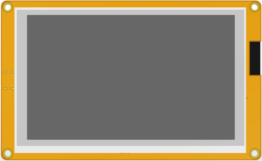
ES3R50T-TopView
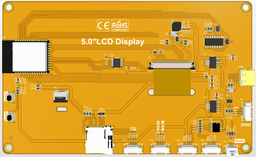
ES3R50T-BottomView


Product Introduction
- Equipped with ESP32-S3 chip, powerful performance and abundant development resources for convenient development
- 5-inch color screen with 800×480 resolution, rich display colors (RGB565)
- Abundant peripheral interfaces for easy connection of SPI, UART and other external devices
- Built-in resistive touch screen for convenient human-machine interaction
- Standard Type-C interface for program uploading and power supply
- Onboard Micro TF card slot for storage expansion
- Built-in audio interface for speaker connection and audio playback
- Complete demo programs provided for easy learning
- Technical support for underlying drivers with online updated WIKI documents
Product Parameters
ESP32 Main Controller Parameters
| Item | Parameter |
|---|---|
| Module Chip | ESP32-S3 |
| CPU | Xtensa LX7 32-bit Dual-Core Processor |
| Max Clock Frequency | 240MHz |
| Storage Resources | 384 KB ROM + 512KB SRAM
+16 KB RTC SRAM + 8M Built-in OPI PSRAM + 16M External QSPI Flash (N16R8) |
| Wi-Fi | 2.4GHz, 802.11b/g/n standard |
| Bluetooth | Bluetooth V5.0 BR/EDR & BLE |
| Core Operating Voltage | 3.0~3.6(V) |
LCD Screen Parameters
| Item | Parameter |
|---|---|
| Screen Size | 5inch |
| Panel Type | TN |
| Resolution | 800xRGBx480(pixels) |
| Active Display Area | 108.00(W)×64.80(H) mm |
| Color Depth | 65K (RGB565) |
| Display Interface | RGB565-16Bit |
| Pixel Pitch | 0.153(H)×0.153(V) mm |
| Viewing Angle | 6 o'clock |
| Typical Backlight Brightness | 450cd/m2 |
| Backlight Type | White LED |
| Operating Temperature | -20~60℃ |
| Storage Temperature | -30~70℃ |
Other General Parameters
| Item | Parameter | |
|---|---|---|
| SKU | ES3R50T | |
| Active Area Size | 5 inch | |
| Supply Voltage | 5.0V | |
| Power Interface | USB Type-C | |
| Typical Total Current | 250mA | |
| Actual Backlight Brightness | 450cd/m2 | |
| Typical Power Consumption | 1.25W | |
| Touch Panel Type | Resistive Touch Screen | |
| Touch Resolution | 800x480(pixels) | |
| Touch Driver IC | XPT2046 | |
| Touch Communication Bus | SPI | |
| LCD Outline Dimension | 120.7(W)×75.9(H)×4.2(D) mm (Excluding FPC cable & adhesive tape) | |
| Touch Panel Outline Dimension | 117.5(W)×70.2(H) mm (Excluding FPC cable & adhesive tape) | |
| Module Overall Dimension | 137(W)×84(H)×13.75(D) mm | |
| Operating Temperature | -20~60℃ | |
| Storage Temperature | -30~70℃ | |
| Weight (Including Package) | Resistive Version (ES3R50P): 197 g | |
Interface Definition

Interface Function Description
| Interface No. | Function Description |
|---|---|
| ① ESP32-S3 Chip | Main controller of the display module, responsible for controlling onboard and external peripherals. |
| ② MicroSD Card Slot | For Micro SD card insertion to expand storage space, to store large-capacity files such as font libraries, pictures and audio files. |
| ③ UART Port | 1.25mm 4P connector, used for serial debugging, firmware uploading and data communication. |
| ④ BOOT Button | Used to enter download mode or as a normal test button.
Hold this button while powering on the module then release to enter download mode; Or keep holding BOOT after power-on, press and release the RESET button, then release BOOT to enter download mode. It can work as a regular button when download mode is not required. |
| ⑤ Type-C Port | Main port for power supply and firmware uploading. Connected with auto-download circuit, which can automatically switch to download mode without pressing the BOOT button. |
| ⑥ RESET Button | Reset pin for ESP32-S3 main chip and LCD screen, active low when pressed. |
| ⑦ Extended Input Header | 1.25mm 4P connector, leads out GPIO17 & GPIO18 pins. |
| ⑧ UART1 & USB Header | 1.25mm 4P connector, leads out GPIO17, GPIO18, GPIO19, GPIO20 spare pins. GPIO17/GPIO18 for UART1; GPIO19/GPIO20 for USB differential signals. |
| ⑨ SPI Peripheral Header | 1.25mm 4P connector for external SPI devices, shared with SD card bus. Can be used as general GPIO when SPI peripheral is idle. |
| ⑩ Speaker Header | 1.25mm 2P connector for speaker connection and audio playback. |
ESP32 Pin Assignment Table
| On-board Device | ESP32 GPIO Pin | Pin Function Description |
|---|---|---|
| LCD Screen | IO40 | LCD chip select signal, active low |
| IO46 | Data Enable (DE) Control Pin | |
| IO41 | Vertical Sync (VSYNC) Control Pin | |
| IO39 | Horizontal Sync (HSYNC) Control Pin | |
| IO42 | Pixel Clock (PCLK) Control Pin | |
| IO45/48/47/21/14 | 5-bit Red Data Pins | |
| IO5/6/7/15/16/4 | 6-bit Green Data Pins | |
| IO8/3/46/9/1 | 5-bit Blue Data Pins | |
| Resistive Touch Screen | IO12 | SPI Clock (SCLK) for XPT2046 touch IC |
| IO13 | SPI MISO (Master Input, data read) | |
| IO11 | SPI MOSI (Master Output, data write) | |
| IO38 | Touch SPI Chip Select (CS) Pin | |
| MicroSD Card | IO10 | SD Card SPI Chip Select (CS) Pin |
| IO11 | SD SPI MOSI (Master Output, data write) | |
| IO13 | SD SPI MISO (Master Input, data read) | |
| IO12 | SD SPI Clock (SCLK) Pin | |
| Buttons | IO0 | BOOT strapping button: hold during power-on to enter download mode |
| EN | Global active-low reset pin (shared for ESP32-S3 and LCD) | |
| UART0 | RXD0(IO43) | UART0 receive pin, usable as general GPIO if serial is unused |
| TXD0(IO44) | UART0 transmit pin, usable as general GPIO if serial is unused | |
| External SPI Header | IO19 | External SPI chip select pin, general GPIO available if USB function is disabled |
| IO11 | SPI MOSI pin, general GPIO available if SD card is unused | |
| IO13 | SPI MISO pin, general GPIO available if SD card is unused | |
| IO12 | SPI SCLK pin, general GPIO available if SD card is unused | |
| Extended GPIO Pins | IO18 | General GPIO when touch & audio & SD card are disabled |
| IO17 | General GPIO when audio & SD card are disabled | |
| USB Interface | IO19 | USB D- differential data line |
| IO20 | USB D+ differential data line | |
| UART1 | IO17 | UART1 transmit pin |
| IO18 | UART1 receive pin | |
| I2S Audio Speaker Interface | IO18 | I2S Left/Right Clock (LRCLK) Pin |
| IO17 | I2S Serial Data (SDATA) Pin | |
| IO0 | I2S Bit Clock (BCLK) Pin |
快速使用说明

资料包下载
百度云盘备份链接2: 2.8寸ESP32-S3-ILI9341驱动显示模块资料包(提取码:yvne)
产品文档
规格书
产品规格书
用户手册
尺寸图
原理图
